


4
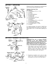
SECTION 1: UNPACKING
Figure 1
Figure 2
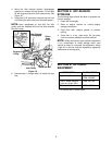
Remove the tiller, all loose parts and hardware pack
from the carton before discarding the carton.
Contents of Hardware Pack:
(See Figure 2)
For shipping purposes, the engine oil dipstick has
been placed between the engine and the gas tank.
Insert dipstick into oil fill tube before operating the
unit.
SECTION 2: ASSEMBLY INSTRUCTIONS
Figure 3
Figure 4
IMPORTANT: This unit is shipped WITHOUT
GASOLINE or OIL. After assembly, service
engine with gasoline and oil as instructed in the
separate engine manual packed with your unit.
NOTE: Reference to right or left hand side of the
mower is observed from the operating position.
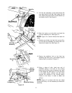
1. Place spacer (K), then one flat washer (D) over
swivel wheel shaft. Place swivel wheel in
position on tiller. See Figure 3. Next, place
other flat washer (D) over swivel wheel shaft.
Secure with hairpin clip (E). See Figure 3.
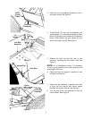
2. Assemble the stabilizer link to front of chain
case on tiller. Secure with shoulder bolt (H),
lock washer (L) and hex nut (G). See Figure 4.
Extension
Spring
Link
Rod
Assembly
Stabilizer
Link
Hitch
Bar
Assembly
Swivel
Wheel
A
B
C
H
I
J
G
E
D
F
E
M
N
A (1) Flat Washer 1/2" I.D. x 1" O.D.
B (1) Sleeve
C (1) Ferrule
D (2) Large Flat Washers
E (3) Hairpin Clips
F (1) Hairpin Clip
G (1) Hex Nut 5/16-18 Thread
H (1) Shoulder Bolt
I (1) Clevis Pin
J (1) Flat Washer 1/2" I.D. x 15/16" O.D.
K (1) Spacer (Not Shown)
L (1) Lock Washer (Not Shown)
M (1) Flat Wash 5/8 ID x 1 1/4 OD
N (1) Hairpin
Flat
Washer (D)
Spacer (K)
Swivel
Wheel
Shaft
Hairpin
Clip (E)
Flat
Washer (D)
Stabilizer
Link
Lock
Washer (L)
Hex Nut
(G)
Shoulder Bolt (H)