


ASSEMBLY
TM60/72/84/100 02/11 Assembly Section 3-4
© 2011 Alamo Group Inc.
ASSEMBLY
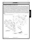
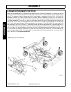
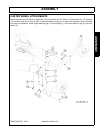
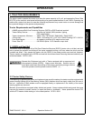
A-FRAME ATTACHMENT FOR TM100
Attach the rear brace bars (1) to the rear of the deck with 5/8 x 2 bolts (2), flatwasher (3), bushing (4) and 5/8
locknut (5). Insert weldment (6) between double lugs on deck and pin in place using pin (7) and cotter pin (8) in
hole “D” of weldment. Attach A-frame bars (9) to inside holes in weldment (6) using 7/8 x 2-1/2 bolt (10),
flatwasher cotter pin (8). Attach A-frame bars (9) to inside holes in weldment (6) using 7/8 x 2-1/2 bolt (10),
flatwasher (11), bushing (12), and 7/8” nut (13). Insert top link bushing (14) between upper end of A-frame bars
(9). Install flatwasher (3) onto 5/8 x 5 bolt (15), and insert through link bar (16) through top link bushing (14)
and link bar (16) on side, and install 5/8 locknut (5). Insert 5/8 x 2-1/2 bolt (17) through hole “C” in rear brace
bar (1), then insert two bushings (18) through opposite rear brace bar (1) and 5/8 locknut (5). Insert washer (3)
then bushing (4) on 5/8 x 2-1/2 bolt (17). Insert bolt through top hole on rear brace bar (1) and through hole “A”
on link bar (16), then through opposite rear brace bar (1), bushing (4), flatwasher (3), and 5/8 locknut (5). Insert
5/8 x 2-1/2 bolt (17) through bushing (4), link bar (16) hole “B” another bushing (4) then 5/8 lock nut (5). Insert
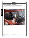
pin (19) through top holes in A-frame bar (9), and lock with lynch pin (20). Insert pin (21) into weldment (6).
Lock into place using pin (22). If A-frame needs to be extended out for clearance purposes, move holes A to E,
B to F, and D to G. See Figure Asm-R-0447.