


MAINTENANCE
TM60/72/84/100 02/11 Maintenance Section 5-12
© 2011 Alamo Group Inc.
MAINTENANCE
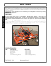
PARTS INSPECTION
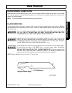
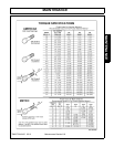
Inspect and clean all parts. Check bearings, shafts, gears, housing, and cover. Shafts should be inspected at
seal wear areas, bearing areas, splines, and threads. Check housing for cracks and condition of threaded
holes. If bearings are replaced always replace both cup and cone. Inspect gears for excessive wear on teeth,
pitts, and gouges. Replace as necessary. always replace both gears for best performance. Check all seal
bores for scratches or nicks which will damage seal when installed. File all damaged areas.
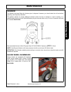
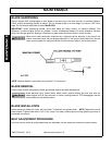
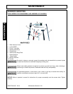
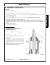
OUTPUT SHAFT INSTALLATION
1. Install shim kit (6) onto output shaft (20) and press bearing cone (7) under gear as far as possible.
2. Install both bearing cones (7) into housing. Insert output shaft into housing.
3. Install lower bearing cone (7) and locknut (8). tighten locknut until bearings are pre-loaded to 10 to 15 inch-
pounds. Set lock portion of nut using punch. Drive or form lower portion of nut into groove in shaft. Nut
must be locked or it will back off during operation. For added protection a thread locking compound may be
added to nut during assembly. Mnt-R-0306
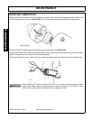
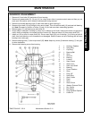
INPUT SHAFT INSTALLATION
1. Drop gear (17) into housing from top. Insert input shaft through housing and gear.
2. Place shim kit (14) and rear ball bearing onto shaft. Press bearing into housing and install retaining ring (2).
3. From opposite side of housing press bearing cone onto shaft against gear. Press bearing cup into housing.
Install shim (5) and install retaining ring (2). If ring will not go into groove in housing remove shims until ring
can be installed.
4. Tap on both ends of shaft to seat bearings. Grab spline end of shaft and exert a push and then pull force. If
movement is observed shim (5) must be added. Repeat until no movement is observed.
5. Check gear backlash by grasping both shafts and then rotating one shaft back and forth so gear is hitting
on one side and then the other. If no backlash is noted then shim (14) must be increased and shim (5)
decreased by same amount. If dial indicator is available backlash can be measured by placing indicator on
gear tooth through top cover opening. Backlash should be 0.015 to 0.020 inch. If excessive backlash is
noted reverse procedure noted earlier. Mnt -R-0306
ASSEMBLY COMPLETION
1. Install input and output shaft seals. Use caution when installing to avoid damaging seal lip. Lubricate seal
lip before installing.
2. Install rear input seal plug.
3. Set box upright and fill with proper amount of gear lube.
4. Install and seal with gasket sealer and top cover. torque bolts to proper torque. Gearbox assembly is
complete.