


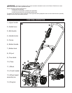
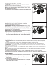
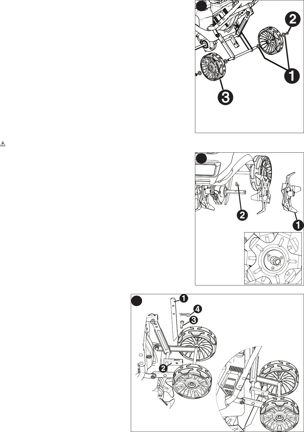
WHEEL ASSEMBLY - (FIGURE E)
1. Place a washer (E-1) on each end of the axle.
2. Place a wheel (E-3) on each end of the axle.
3. Place another washer (E-1) on the outside of the wheel.
3. Thread bolt (E-2) into axle. Tighten securely with a 10 mm or
adjustable wrench.
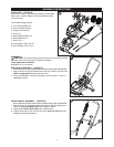
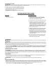
TINE ASSEMBLY - (FIGURE F)
WARNING: Garden tiller tines are sharp. Always wear leather gloves to protect your hands when handling tines.
1. Place a tine (F-1) with the fins facing inward on the axle as shown in
figure F. Place another tine against it with the fins facing out.
2. Insert the long hairpin cotter pin (F-2) through the hole in the end of
the axle as shown in the inset.
NOTE: For tilling in a narrow area, such as between plant rows, it may
be desirable to leave the outer tine pairs off. Unplug the tiller before
removing the outer tine. Ensure that the cotter pin is inserted in the
inner hole location on the axle when only the inner tine positions are
used.
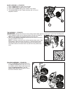
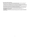
DRAG BAR ASSEMBLY - (FIGURE G)
1. Insert the drag bar (G-1) through the slot in
the drag bar bracket (G-2). Align the hole in
the drag bar with the hole in the bracket and
insert the locating pin (G-3). Push the
hairpin cotter pin (G-4) through the hole in
the end of the bolt to secure.
E
F
G
7