


5
Ensure that the electrical supply cable is
not twisted before you begin to assemble
the handle.
D
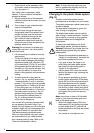
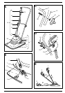
• Locate the two pins on the switch box (13)
with the holes in the upper handle (12).
• Fit the retaining plate (23) over the stem
of the handle (12) ans secure in position
using the two screws (24) provided.
Note: Do not overtighten these screws - light
pressure will be sufficient to hold the switch
box in position.
• Finally, secure the electrical supply cable
to the lower handle using the cable clip
(17) supplied.
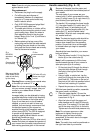
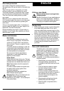
Handle operation (Fig. E)
E
The handle has three positions, two storage
(park) positions and one operating position.
Positions 1 and 3 in Fig. E are the storage
(park) positions and F is the operating range.
For storage purposes, the handle assembly
can be set to position 2 or 3, as follows:
• With the handle in its working range F,
pivot the handle downwards until it
contacts the stops on the end of the
handle tube. This is the park position
2 for the handle.
• The handle can be moved to a park
position 3. Push the handle upwards in
the working range F, to the top position
1. Pull the handle upwards. While still
pulling the handle upwards, pivot the
handle down towards the ground to
position 3.
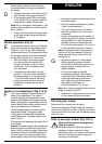
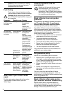
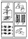
Height of cut adjustment (Fig. F & G)
F
Your mower employs a manual method of
height of cut adjustment. The method
involves changing the arrangement of the
spacers fitted between the impeller and the
blade, and applies to mowers fitted with the
steel or plastic blade cutting systems which
can be purchased as an accessory.
The following procedure assumes that the
steel blade is fitted. If the plastic blade
cutting system is fitted then take blade to
mean blade carrier. The blade carrier (25) is
shown in Fig. F.
The procedure for adjusting the height of cut
is as follows:
Caution: The plastic blade cutting system has
been designed to maintain lawns at a fixed
length, not for cutting long grass. We strongly
recommend that you use the steel blade to
cut your grass to the required length, then
use the plastic blade to maintain that length.
ENGLISH
• Ensure your mower is disconnected from
the mains supply.
• Place the handle assembly into position
3 (see “Handle operation”).
• Turn your mower over onto its side so
that the underside of the cutter cover
is exposed.
• Using a cloth placed over the blades or
heavy duty gloves to protect your hands,
grip the blade and, using the spanner
provided, loosen and remove the nut
(21) from the motor spindle. Turn the nut
in anti-clockwise direction to loosen it.
Note: If the plastic blade cutting system is
fitted then it will be necessary to grip the
blade carrier (25) firmly to prevent it from
turning (Fig. F).
G
• Remove the blade nut, white washer
(26) (if supplied), spacers and blade
(21-24) and re-assemble to give the cut
height required, showing the 6 cut
heights available.
• Once the cut height is selected,
re-assemble the blade, ensuring the
cutter blade (23) is assembled with the
cutting tips downwards as shown in
Fig. F and ensure the white washer
(26) is fitted to the blade nut.
• Ensure the blade nut (21) is tight.
Note: Your mower is supplied with the blade
height in position E (Fig. G).
• Always re-fit 3 spacers and never fit more
or your mower will become unsafe.
Carrying your mower
Disconnect your mower from the mains.
Remove the grassbox (if fitted), lower the handle to
the flat “park” position and then, holding one handle
near the pivot block and carry with the blade pointing
away from you.
How to use your mower (Fig. H & J)
!
Observe all the relevant warnings when
using your mower.
We recommend the directional method of
operation to obtain maximum cutting
performance from your mower and to reduce
the risk of the trailing extension lead from
entering the cutting path.