


4
B3
• When both handles are assembled, fit
one cable clip (18) onto the upper handle
and one onto the lower handle. Clip the
cable into these ensuring the grassbox
can be removed and positioned freely.
Grassbag assembly (Fig. C)
Note: Ensure the battery is disconnected.
Read the safety instructions at the beginning
of this manual before using this accessory.
C1
• Before starting to assemble the grassbag,
check that the parts are similar to those
shown in Fig. C1.
• Secure the grassbag by inserting the bag
rim into the channel and pushing down
firmly until the clip feature locks onto the
bag rim (inset).
C2
• Push the support frame firmly into place.
C3
• Assemble the two side clips to the
support frame, then assemble the
bottom clip.
Battery information
• The battery in your cordless lawnmower is a
12 volt sealed lead acid system. The battery
employs an absorbed electrolyte and, can
therefore, be stored in any position without
fear of leakage.
• The battery has been charged at the factory,
however, it will be necessary to recharge the
battery to ensure full charge before initial use.
• For optimal performance the battery should
be recharged after each use.
• For winter storage ensure:
• The mower is fully charged before storing.
• The temperature of the storage location is
below 25˚C.
• Storage duration is less than 6 months.
• Always store your mower in a dry and
cool location.
• Keep the mower and battery away from water,
heat sources (such as radiators, heaters, stoves
etc.), flames or chemicals.
Battery strap
• Locate the battery and its carrying strap.
• Fold the sides of the strap up and put the battery
in place.
• Click the straps together ensuring you locate
every hole.
• The strap should be kept on the battery at all times.
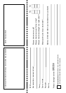
Unpacking and assembly
Your mower carton contains:
• The mower and handle assembly.
• One hardware bag containing:
• Two safety keys (24).
• Instruction literature.
• Blade nut spanner (25).
• Charger (26).
• Battery strap (27).
• One grassbag assembly (19) - see below for
assembly instructions.
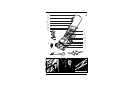
Handle assembly (Fig. A & B)
A
Remove the contents of the carton and
familiarise yourself with the individual parts of
the mower.
The main parts of the mower shown in Fig. A
are as follows:
• Machine body (1):
• Cutter deck (2)
• Motor cover (3)
• Battery cover (4)
• Grass flap (5)
• Wheel assembly (6)
• Pivot pin (7)
• Grill (8)
• Handle (9):
• Upper handle (10)
• Lower handle (11)
• Handle knob (12)
• Switch lever (15)
• Switch box (16)
• Electric cable (17)
• Retaining clips (18)
• The lower handle (11) comes ready
assembled to the mower body.
B1
• All that is required is to unfold the handle
by lifting it until the handle ends snap into
their locations on the sides of the mower.
Once this is complete the knobs (12) can
be tightened.
B2
• The upper handle (10) is assembled by
fitting the bolts (13) through the holes in
the lower handle, aligning the upper
handle over these and securing with a
washer (14) and then the knob (12).
• Tighten each one with hand pressure only.
Do not use a spanner.