


Part No. 890604 Form No. F021602C
Page 9 of 12
MAINTENANCE continued
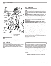
IMPELLER REMOVAL continued
18. If chipper blade properly clears anvil surface, proceed to step .
If not, return to (step 14) and add or subtract shim washers as
needed to obtain a correct gap.
19. Reinstall engine and impeller onto housing in reverse order
of removal.
20. Before connecting spark plug wire, slowly pull engine
starting rope to insure that impeller rotates freely.
21. Reinstall spark plug wire.
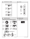
fig. 7
17
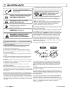
Engine (See Engine Manual)
Check for excessive vibration
Clean Debris Bag
Check bag strap tightness
Inspect for loose parts
Maintenance Operation
Follow these hourly
maintenance intervals.
Maintenance Schedule
Inspect for worn or damaged parts
Every 5 hrs
or (Daily)
Every
Use
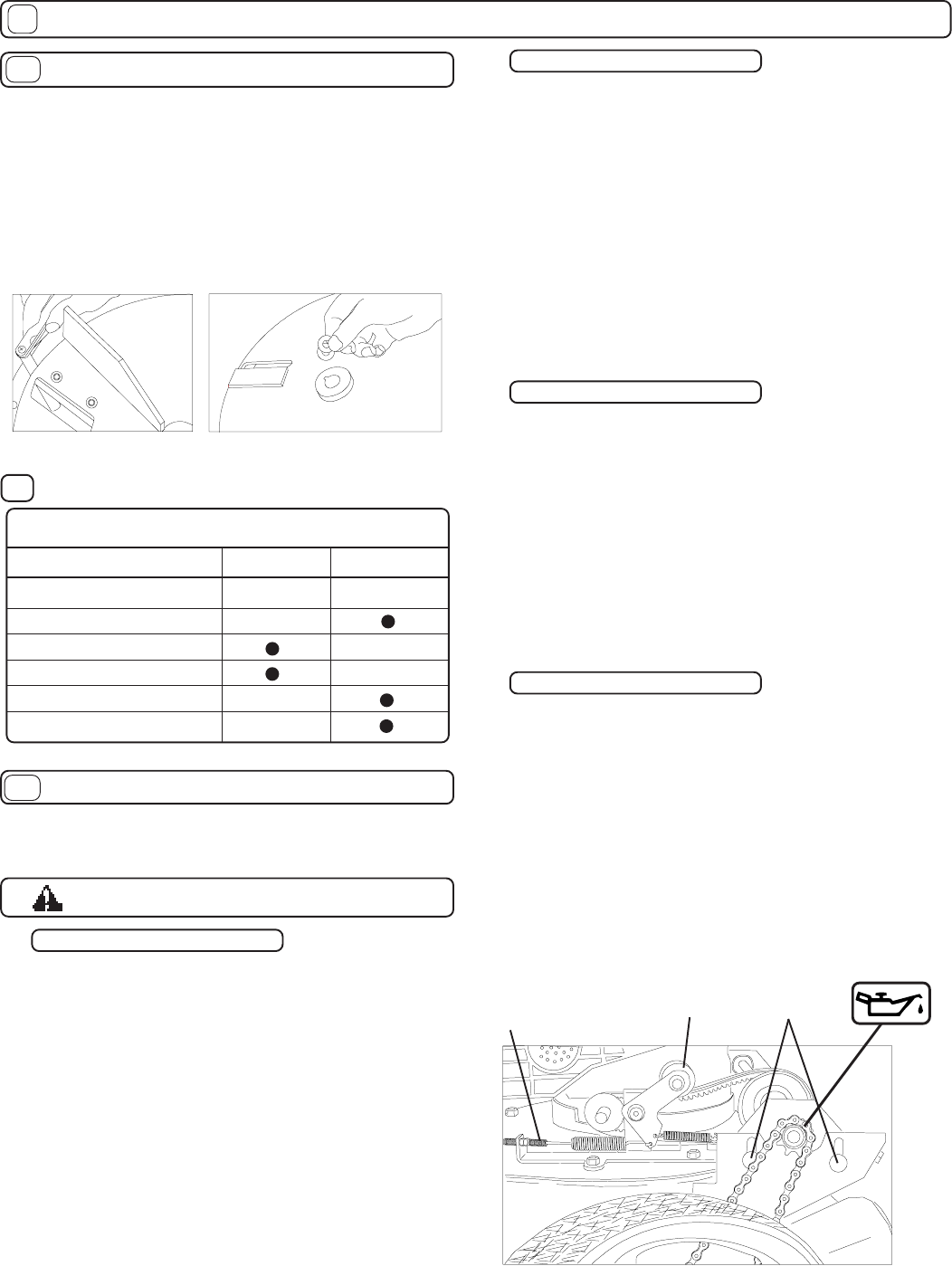
17.2
Threaded
Adjuster
Carriage
Bolt
Idler
Pulley
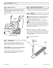
CLUTCH ADJUSTMENT
INSPECTING DRIVE
CHAIN ADJUSTMENTS
DRIVE
Chains are normal replaceable wear items. A new chain
should not be used on worn sprockets. Sprockets should
be replaced when replacing chains.
Stop engine and disconnect spark plug
wire before making adjustments.
17.3
17.1
fig. 6
1. Remove chain guard
2. Inspect chains, sprockets, belt, and pulleys for wear and
replace as required
3. Inspect chains for lubrication and lubricate as required
4. Check chain tension. A properly tensioned chain will
deflect about 1/8” midway between the sprockets when
light and pressure is applied. If adjustment is required see
Replacing and adjusting chairs.
5. Check clutch adjustment. When properly adjusted,
operating the clutch at the handle will move the idler pulley
down such that a gap of 5/8”-3/4” is left between the inside
halves of the belt. Worn belt or pulleys can give the
appearance of clutch mis-adjustment. Replace any worn
components. If adjustment is required see Adjusting
clutch cable.
6. Replace guard after inspection.
CHAIN REPLACEMENT
When replacing always replace both chains even if only one
appears worn.
1. Remove chain guard
2. Loosen (4) carriage bolts that hold the jackshaft bearings in
place.
3. Slide the jackshaft down and back toward the engine to
loosen the chains.
4. Remove nuts that hold the front wheels.
5. Slip chains off the small sprockets on the jackshaft and slide
the wheel and chain off each side.
6. Replace the chains on the wheels and reinstall them on the
axles.
7. Slip chains over the small sprockets on the jackshaft.
8. Adjust chains for proper tension (see below)
9. Check clutch for proper operation and adjust if required.
1. Loosen (4) carriage bolts that hold jackshaft bearing on
place.
2. Pull up on jackshaft to draw chains tight
3. While holding chains tight rotate the jackshaft back toward
the engine slightly so that there is no tension on the belt.
NOTE: If the jackshaft is set too far forward the belt will not
clutch or release properly during use.
4. With jackshaft properly positioned tighten (4) carriage bolts to
lock it in place.
5. Rotate wheels by hand and check chain tension and align-
ment.
6. Readjust as required.
7. Replace guard.
1. Remove guard.
2. To increase belt tension (drive will not engage) loosen jam
nuts that hold the treaded adjuster on the clutch cable.
3. Slide the adjuster toward the rear of the unit about ¼” and
retighten the jam nuts, to secure it in place.
4. Test clutch operation and readjust as required
5. To decrease belt tension (drive will not disengage or free
wheel) loosen jam nuts that hold the treaded adjuster on the
clutch cable.
6. Slide the adjuster toward the front of the machine about ¼”
and retighten the jam nuts to secure the cable in place.
7. Test clutch operation and readjust as required.
8. If unit will not free wheel with clutch disengaged loosen (4)
carriage bolts and slide the jackshaft back 1/8” and retighten
carriage bolts.