


Part No 520187 Form No F010408A
9
FM Owner’s Manual
ASSEMBLY
NOTE: All item numbers called out in the assembly, operation, and
maintenance sections of this manual can be found on Parts List
(pages 15-18).
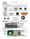
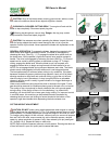
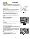
1. Cut and remove the nylon retaining straps (see figure 11-1).
2. With the console and handle assembly positioned as shown in
Figure 11-3, insert the shift linkage rod (Item 31) into the shift
linkage connector (Item 54).
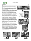
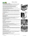
3. To assemble the shift rod (item 31) to the shift linkage (item 54),
use the roll pin in the parts/literature bag. If you’ll notice on the shift
linkage, the hole is larger on one side than the other.
It will be easier to start the roll pin from the larger side, forcing it
through the shift rod and the hole on the other side of the shift
linkage, using a hammer or large adjustable pliers.
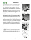
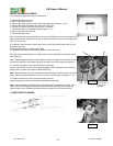
4. Insert one of the handle mounting bolts (Item 102) with split lock
washer (Item 6) on top of flat washer (Item 184) through the rear
handle mounting hole of the right side handle, and screw it into the
rear handle mounting hole on the right side of engine base chassis
(Item 61). Repeat this procedure for the left side using the left
handle.
5. On each side of the mower, insert one of the handle mounting
bolts (Item 102) with split lock washer (Item 6) on top of flat washer
(Item 184) through the hole in one end of the handle brace (Item
32), the front handle mounting hole of the handle and screw into the
front handle mounting hole in the engine base chassis (Figure 11-5).
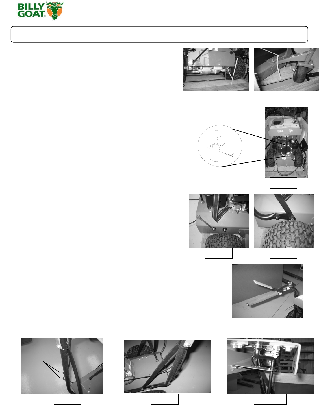
6. Attach the blade lever using the clevis pin, two washers and the
pal nut from the parts bag. Align the lever to the hole on the handle
and place a washer on the pin and slide it through. Then put a
washer on the other side and gently tap the pal nut onto the end of
the pin. (See fig. 11-7)
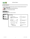
7. Position control cables and use 2 cable ties on each handle to
secure the cables in position. The top cable tie should be 1” below
the console and the lower tie should be 12” below the console (see
figure 11-8 and 11-9).
8. Check the position of the shift rod guide (Item 69), and if
necessary, snap it in place in the shift bracket (Item 78) as shown in
Figure 11-10.
9. Put shift lever in NEUTRAL, depress the brake lever (release the
brake) and carefully pull the machine back off the pallet.
10. Fill with oil and gas to the proper level and the unit is ready to
mow. (A battery will also have to be installed.)
11. Read the operator’s manual.
Fig. 11-1
Fig. 11-3
Fig. 11-4 Fig. 11-5
Fig. 11-7
Fig. 11-10 Fig. 11-9Fig. 11-8
Shift rod
Shift
linkage
Roll Pin
Cable
ties