


Part No 520187 Form No F010408A
14
FM Owner’s Manual
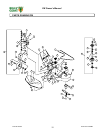
BELT REPLACEMENT
When replacing one belt the other should be inspected for wear and replaced if worn. It
is good practice to change both belts when either is worn beyond use. Use only original
equipment belts for replacement. Billy Goat uses only premium quality, Kevlar corded
and coated belts in your unit. Substitute belts do not meet the design and performance
requirements for your unit, and will greatly reduce machine performance and belt life.
Blade Drive Belt
Tools required: ratchet, 3/4 inch socket, 10” extension bar for socket, two ½” wrenches
and adequate support for machine.
1. Disconnect spark plug wire.
2. Remove the deck belt cover.
3. Support front of unit to allow access to underside of the machine near the engine.
Note: Unit is heavy. Be sure support is adequate to prevent personal injury.
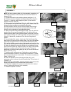
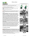
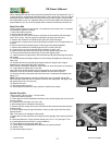
4. Observe the orientation of the belt fingers (Item 90) under the engine.
5. Remove the 4 engine mount bolts (Item 48) being careful not to let engine slide out
of place.
6. Remove the left and right belt fingers (These fingers are interchangeable).
7. Observe the orientation of the belt finger (Item 91) on idler (Item 50).
8. Loosen but do not remove idler/belt finger retaining nut (Item 144).
9. Observe belt routing and remove the belt from front spindle pulley (Item 46).
10. Remove the belt from the idler pulley and from the engine pulley.
11. Install new belt on engine pulley, idler and front spindle pulley following the original
belt routing.
12. Position the idler belt finger centered on idler bracket and tighten the retaining nut
(Item 144).
13. Reinstall the left and right belt guide fingers under the engine base using all
fasteners in the exact order they were removed.
NOTE: Before installing the fasteners inspect them for wear and replace as necessary.
14. Torque the four engine bolts to 40 ft-lbs.
Note: With clutch levers engaged, be sure belt guides do not touch belts after
installation, there should be 1/8” clearance between the belt and the guides.
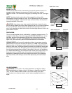
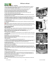
15. Observe the idler pulley when the blade drive lever is lowered and released (see
figure 17-7).
NOTE: Idler should tighten the belt when blade drive lever is pressed and the belt
should be slack when the lever is released. With the lever depressed, the edge of the
belt guide should not rub on the belt.
16. Replace the cover
17. Reconnect spark plug wire.
18. Start engine and check for proper operation of blade drive system.
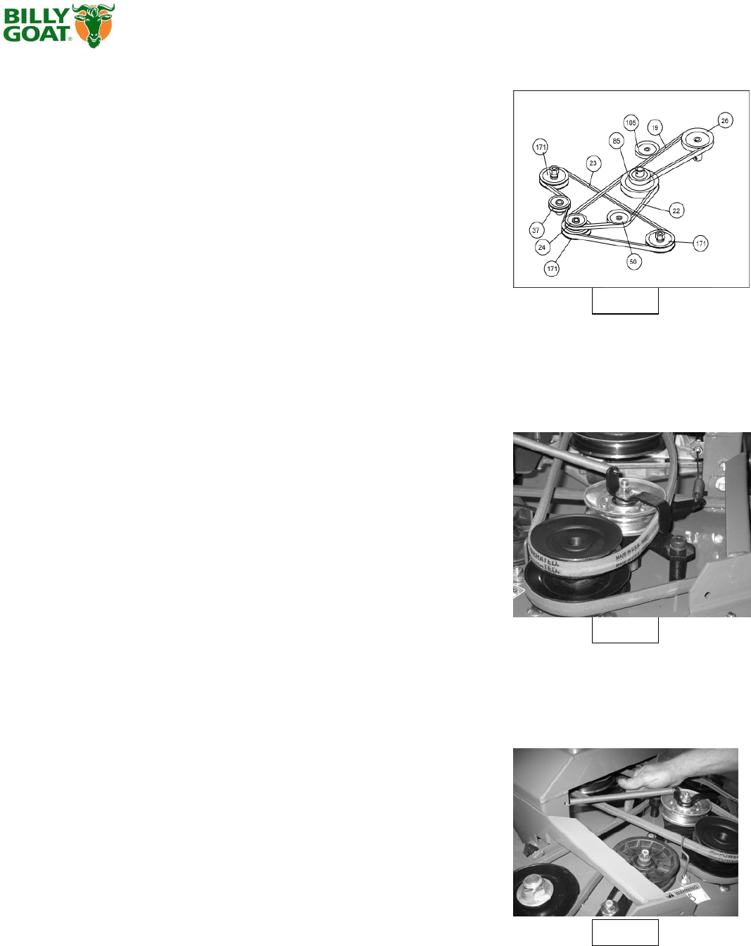
Fig. 17-6
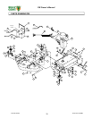
Spindle Drive Belt
Tools required: 3/8 inch socket, 1/2 inch socket.
1. Disconnect spark plug wire.
2. Follow steps to remove the Blade Drive Belt (on the spindle pulley side only) from the
previous section.
3. Loosen the two idler plate nuts (Item 143).
4. Slide the belt idler to release the belt tension.
5. Observe the belt routing, then remove the old belt and install the new belt using the
original routing.
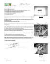
6. Tension the belt using a long screwdriver or other pry bar to push the idler pulley
against the belt.
Note: Take care not to damage the idler pulley.
7.Tighten the two idler plate nuts just enough to avoid slippage while checking the belt
tension.
8. Check belt deflection. Finger pressure should give 0.5” to 0.75” (see figure 17-8).
9. Increase/decrease belt tension for proper deflection.
10. Finish tightening the two idler plate nuts.
11. Follow steps to reinstall Blade Drive Belt from the previous section.
12. Replace cover.
13. Reconnect spark plug wire.
Fig. 17-7
Fig. 17-8