


Part No 440271 Form No F070809A
9
FORCE BLOWER Self-propelled Owner’s Manual
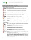
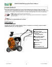
ASSEMBLY
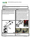
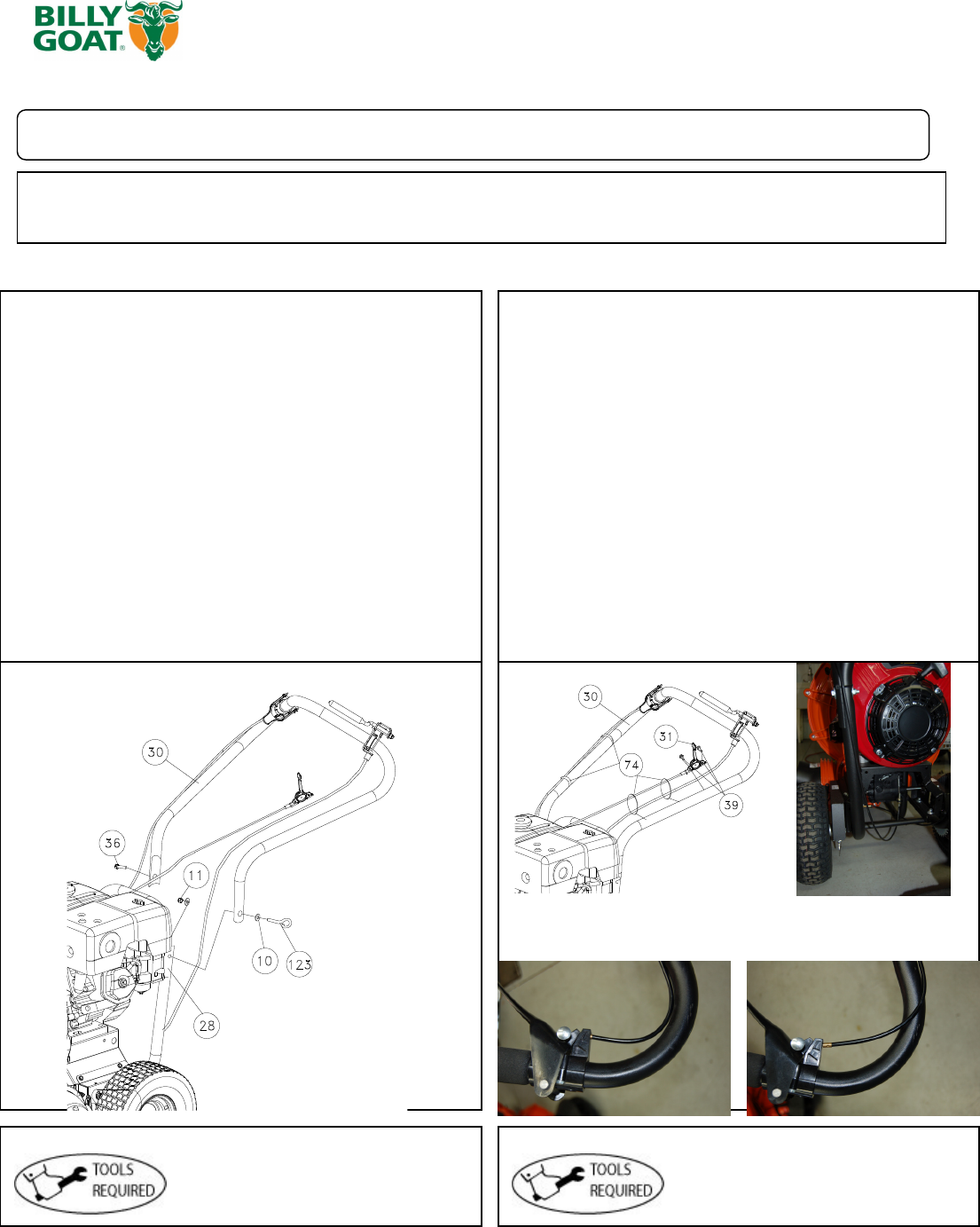
Figure A Figure B
1
.Follow the steps in figures A and B, then securely tighten all hardware shown.
2.Connect spark plug wire.
The hardware for attaching the upper handle to the lower is in
the parts bag. Install upper handle (item 30), to preassembled
lower handle (item 28) by sliding the upper over and down the
outside of the lower handle. Using bolt (items #36 and 123),
washers (item #10) & lock nut (item #11) to install upper handle
to lower handle. Note: The Pigtail bolt should go on the side
that the pull start is on and the open end should be faci
ng down.
Finish installing the other side of the upper handle assembly
using screw and lock nut provided.
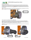
The throttle control will be attached to the throttle arm on the
engine and wrapped around the engine for shipping. Unwrap
and secure throttle control (item #31) to upper handle with
screws (item #39). Screws will already be mounted in handle,
simply remove and use to mount the throttle control. Secure the
throttle cable and clutch cable with two Ty-wraps. The Aim-and-
Shoot
TM
is not attached, you will need to unroll the cable and
attach the ball end to the lever and seat the cable end into the
hole on the saddle clamp, with the cable running through the
slot. The Clutch cable will also be wrapped up under the
machine. Route the cable under the axle and attach it by
removing the hitch pin and clevis pin and attaching it to the
clutch control lever. After it is attached pull on the cable and
slide it into the hole on the bracket so that it clicks into place. To
keep the cable from being damaged use three ty-wraps (item
74) to secure it to the handle as shown making sure that the
cable is not rubbing against the tire. Note:
the cable should
be seated properly in the saddle and should follow the
contours of the handle.
Two ½” open ended wrenches
One 5/16 open ended wrench
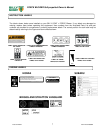
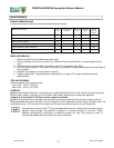
Good routing Bad routing