


Receiving & Installation 3-11MN2408
Battery Charger Considerations
1. Mount the battery charger on the generator or as close to the generator as possible.
2. If you mount the battery charger inside the building, mount it near the main breaker box
or disconnect box.
3. If you mount the battery charger outside, you must protect it from the environment and
the elements.
4. Do not mount the battery charger where flammable liquids or vapors are present.
General Wiring Considerations
1. When routing the interface wiring, do not route it up against anything that could cut or
chafe the wiring. do not route the wire up against any hot or potentially hot object.
2. Make sure that all the electrical components (generator set, transfer switch, battery
charger, etc.) share a common hard wired ground.
3. Check with your local building inspector to determine what you must do to comply with
the local regulations for grounding of this type of permanent installation.
Frame Ground Connection
WARNING: Be sure the system is properly grounded before applying power. Do not apply AC power
before you ensure that grounds are connected. Electrical shock can cause serious or fatal
injury. NEC requires that the frame and exposed conductive surfaces (metal parts) be
connected to an approved earth ground. Local codes may also require proper grounding of
generator systems.
It is important for safety reasons that the Generator set, transfer switch and battery charger share
a common Ground and neutral.
The NEC requires that the frame and exposed metal surfaces be at local ground reference
potential to avoid electrical shock hazard. A local ground reference may require a driven earth
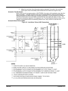
ground conductor at the generator installation site. Make the ground connection as shown in
Figure 3-5. Use the appropriate size wire as required by NEC and local codes.
Warning: Do not connect the generator output neutral to the frame or local ground. The generator
output is isolated from ground. NEC and local codes require that the generator output remain
isolated from local ground reference.
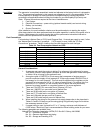
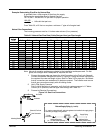
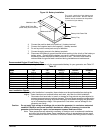
Figure 3-5 Frame Ground Connection
Earth Ground
Frame
Stud
Washer
Ground Wire Lug
Nut
Washer
1. Open the enclosure access panel door 2 ( Figure 3-2).
2. Connect the ground wire to the “earth ground” terminal shown in Figure 3-5.
This ground is the local reference ground to ground the generator frame only.