


General Information 2-13MN2408
Remote Radiator Cooling
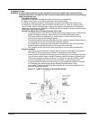
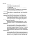
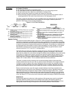
Remote Radiator Airflow generally assumed there will be no external restrictions to airflow. If this
is not true, restriction must be considered in sizing and selection of a cooling fan and drive motor.
Typical examples of restrictions include landscaping, nearby buildings, air turbulence created by
buildings or other structures, and sight or noise “screens”. See Figure 2-9.
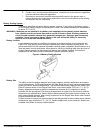
Remote Radiator Fan Motor. Remote radiator cooling systems require the use of an electrically
driven fan. This fan must be connected to the emergency power source. Size of the motor is
determined by the fan size and fan speed.
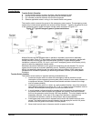
1. To specify a radiator to cool the coolant you will need to determine the amount of heat
rejected to the coolant. This is listed on the Engine Data Sheet as Heat Rejected to
Coolant in BTU/min. for engines using dry or water cooled type exhaust manifolds, as
applicable.
2. Determine the minimum water flow required at the engine, and the maximum top tank
temperature. Using this information, determine the heat rejection capacity required of
the radiator. Radiator systems should be sized with approximately 15% greater
capacity than the engine’s maximum full load heat rejection to allow for overload and
cooling system deterioration. Whether water flow is produced by an engine mounted or
auxiliary pump, total piping system friction loss must be calculated. To do this, genset
location, remote radiator location and friction loss within the radiator, and piping system
must be estimated.
3. Pressure drop through the radiator must be obtained from radiator manufacturer.
4. If total piping system pressure exceeds the allowable Maximum Coolant Friction Head
External to the engine as listed on the Engine Data Sheet, the coolant piping size
should be increased and/or a radiator with less restriction must be used.
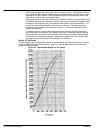
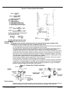
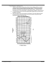
5. Pressure drop in pipelines may be determined by the use of information in Table 2-2
Figure 2-11, and friction of water tables which may be found in most mechanical
handbooks such as “Cameron Hydraulic Data” handbook.
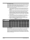
Table 2-2
Fitting Size Flow Restriction of Fittings Expressed as Equivalent of Straight Pipe (in inches)
g
1.5 2 2.5 3 4 5 6 8 10 12 14 16
90 Elbow 4.4 5.5 6.5 8 11 14 16 21 26 32 37 42
45 Elbow 2.5 3 3.8 5 6.3 7.5 10 13 15 17 19
Long Sweep Elbow 2.8 3.5 4.2 5.2 7 9 11 14 17 20 24 27
Close Return Bend 13 15 18 24 31 37 51 61 74 85 100
Tee–Straight Run 3.5 4.2 5.2 7 9 11 14 17 20 24 27
Tee–Side Inlet or Outlet 9.3 12 14 17 22 27 33 43 53 68 78 88
Globe Valve Open 55 67 82 110 140
Angle Valve Open 27 33 41 53 70
Gate Valve Fully Open 1.2 1.4 1.7 2.3 2.9 3.5 4.5 5.8 6.8 8 9
Gate Valve Half Open 27 33 41 53 70 100 130 160 200 230 260
Check Valve 19 23 32 43 53
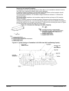
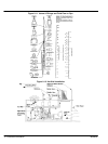
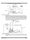
Hot Well Installations
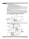
One final consideration on the water side is the Maximum Static Head. This is the maximum
height allowable from the engine crank center line to the highest point in the coolant system. The
maximum static head is specified on generator specification sheets. If this number must be
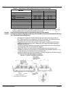
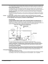
exceeded, a hot well tank system must be used. A typical example is shown in Figure 2-12.
The design of hot well tanks and piping systems is somewhat complex. Your authorized Baldor
Distributor has experience in the design and installation of hot well systems. Consult your Baldor
Distributor if the static head of the coolant system in your genset application exceeds this criteria
and requires a hot well system.