


3-6 Receiving & Installation MN2408
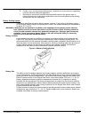
Installation
The generator is completely assembled, tested and adjusted at the factory before it is shipped to
you. The procedures presented in this manual are suggestions and it is the responsibility of the
Owner/Operator to arrange for these procedures to be performed by licensed contractors
according to all applicable codes including local codes for your Municipality/City/County and
State. External connections required at the time of installation are:
1. Fuel System.
2. Electrical Connections – power wiring (optional transfer switch) and control wiring.
3. Battery (not included).
4. Ground Connection.
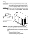
After installation, the post installation checks must be performed prior to starting the engine.
After these checks have been performed and the system operation is verified to be good, refer to
Section 5 Maintenance for periodic checks that must be performed at scheduled intervals to
ensure continued operation with minimal problems.
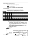
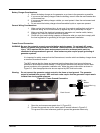
Fuel Connections
Fuel selection is Natural Gas or LPG (Liquid Propane Gas). If natural gas supply is used, follow
the “Natural Gas Connections” procedure. If LPG supply is used, follow the “LP Gas
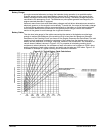
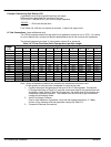
Connections” procedure. Table 3-4 defines the flow rate required for each fuel type.
Table 3-4 Fuel Consumption Natural and LPG
Generator Model Fuel Consumption at 100% load (cubic feet per hour)
Natural Gas LP Gas
GLC30 14.9 5.6
GLC35 16.3 6.0
GLC45 16.5 6.9
GLC50 20.7 8.2
GLC60 22.1 9.1
GLC80 28.7 12
GLC100 32.1 13.8
GLC125 46.8 16.5
General Considerations
1. A generator set needs the engine to deliver 2 hp of energy to the alternator for every
1000 watts of electric output power (example: an 8000 watt generator needs the engine
to deliver 16 hp of energy to the generator end).
2. An engine needs 10,000 BTU’s of fuel energy per horsepower of engine power to
provide a sufficient supply of fuel (example: a 16 Hp engine needs 160,000 BTU’s of
fuel energy for it to work properly). This fuel must be supplied to the regulator on the
generator set at a pressure of 6 oz (11 inches of water column). To achieve this 6 oz.
pressure in a L.P. System, you will normally have to reduce the tank pressure by
means of a primary regulator or a regulator system of 2 or more regulators.
3. There are 2,516 BTU’s in one cubic foot of Propane (LP Fuel).
There are 1,096 BTU’s in one cubic foot of Natural Gas.
4. There are 36.39 cubic feet in one gallon of Propane.
There are 57.75 cubic feet in one gallon of Natural Gas.
5. There are 8.58 cubic feet per pound of Propane.
There are 23.56 cubic feet per pound of Natural Gas.
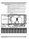
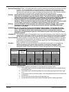
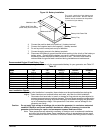
6. When installing the piping for the gaseous fuel supply please refer to the pipe chart in
Tables 3-5 and 3-6 to be sure you are using piping of significantly large size to deliver
the necessary amount of fuel.
7. If copper tubing is used, it should be “K” or “L” having a minimum wall thickness of
0.032 inches. Black Iron Pipe is recommended but follow building codes for your area.
The following pamphlets are available from:
National Fire Protection Association (NFPA) P.O. Box 9101 Quincy, MA 02269
No. 37 – Combustion Engines
No. 54 – Gaseous Appliances and piping
No. 58 – Storage and handling LPG