


General Information 2-17MN2408
Air System
Air System Checklist
A. Air inlet faces the direction of prevailing winds.
B. Air outlet does not face noise sensitive areas without noise attenuating devices.
C. All heat loads have been taken into consideration in sizing air flow.
D. Gravity louvers face inward for air intake and outward for discharge.
E. Where electrically operated ventilation devices are used, power must be present under all
operating situations. Be certain these devices are on the emergency circuit.
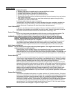
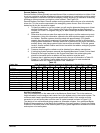
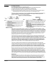
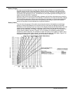
The room in which the generator set is to be installed must have adequate air flow through it to
provide combustion air, and remove heat radiated from the engine, exhaust system and
generator. See Figure 2-14 for air flow calculations.
Figure 2-14 Air Flow Calculations
Radiator Cooling
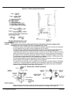
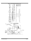
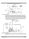
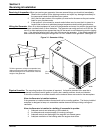
The engine mounted radiator shown in Figure 2-8. With an engine mounted radiator cooling
system, air movement is provided by the engine driven radiator fan. The consultant must design
the inlet and outlet duct work and louvers to accommodate the air flow required. The radiator fan
is limited in the amount of external static pressure it will tolerate. The maximum air restriction on
the discharge side of the radiator is shown under the heading of Cooling System on the Engine
Data Sheets. Cooling fan air flow is listed under Engine Data by dry type and water cooled
exhaust manifold for 100 "F and 125 "F cooling systems.
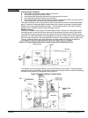
The ideal setup for cooling air would be to arrange the inlet or inlets such that relatively clean,
cool, dry air is drawn across the electrical switchgear, generator, and engine. The air is then
drawn into the radiator fan, and is blown through the radiator and exhausted by duct work outside
the building. Air inlets must be sized to minimize air restriction and provide the quantity of air
required by the radiator fan, engine combustion air, and any other air exhausts which might be
used in the room. On engine mounted radiator cooled systems, the engine mounted fan will
handle 0.25” of water column. This is combined intake and exhaust restriction.
The room air intakes must be located so as to minimize drawing exhaust fumes and other
outside contaminants into the room. Be very cautious about the location of the engine exhausts
in relation to room air intakes. Also, when locating the inlet and outlet, the consultant should
consider prevailing winds and noise. Motor operated louvers or properly designed and sized
gravity louvers should be used on the air intake and exhaust to minimize static pressure drop.
Electric motorized louvers used with engine mounted radiators should be connected to the
standby genset and controlled to open whenever the genset is running. Operable outlet louvers
should be temperature actuated on remote radiator or heat exchanger cooled units. Louvers
have resistance to air flow. Openings with louvers should be twice the area of an unobstructed
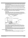
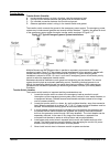
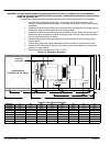
opening to provide proper air flow. At times duct work is necessary to provide cooling air for the
room, see Figure 2-15. Duct work must be sized and installed according to SMACNA Standards.
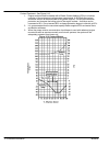
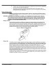
Wind Barrier
Wind blowing against air exhaust or intake openings of the genset room must be considered,
especially where the radiator and fan are located on the engine. Wind blowing against an
exhaust opening creates restriction to the fan. Wind blowing against intake openings can blow
open gravity louvers causing low temperature and moisture problems in bad weather.