


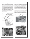
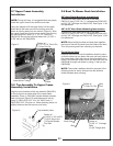
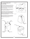

2-2 PTO Assembly Installation
Remove the (2) existing bolts and nuts from the right
side that fastens the mower’s rear frame to the
mower’s chassis. Align the (2) lower holes on the PTO
assembly P#(A0610) (Figure 2) to the (2) lower holes
on the mower’s rear frame. Fasten by using (2) 5/16”-
18 x 1-1/4” Grade 8 HHCS P#(K0118) and (2) 5/16”-
18 flange nuts P#(K1178). Once the PTO assembly is
fastened, drill a hole into the mower’s rear frame by
using the PTO assembly as a pilot and using a 5/16”
drill bit. Fasten by using (1) 5/16”-18 x 1-1/4” Grade 8
HHCs P#(K0118) and (1) 5/16”-18 flange nut
P#(K1178). See Figure 3 for finished installation.
Tighten all nuts and bolts.
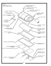
Figure 2.
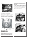
2-3 Belt Installation
Remove the pulley guard P#(B0075) by removing the (2)
1/4”-20 x ½” HHSTS P#(K0353), see page 9, diagram #
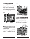
38 and #39 for part location. Loosen the (2) bolts that
secure the gear box assembly P#(A0429) to the PTO
mount plate (Figure 4). Loosen the adjustment bolt
P#(K0348) until the gear box assembly is at the far left
adjustment (the gear box is moved towards the mower’s
engine pulley). Connect the kevlar cord belt from the
engine pulley to the lower gear box pulley (Figure 5).
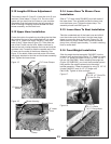
To tension the drive belt, turn the adjustment bolt
clockwise until there is 1” of deflection, with 10-11 lbs. of
pressure between the engine pulley and the gear box
pulley. Once the correct tension of the belt is achieved,
tighten the (2) bolts that secure the gear box assembly.
6
Drill Hole Here & Fasten w/
(1) 5/16” x 1-1/4” G8 HHCS
(1) 5/16” Flange Nut
Mower Rear Frame
PTO Assembly
Fasten Lower PTO Assembly w/
(2) 5/16” x 1-1/4” G8 HHCS
(2) 5/16” Flange Nuts
Gear Box Assy.
Adjustment Bolt
PTO Mount Plate
Engine Pulley
Figure 4.
Figure 5.
Loosen Gear Box Bolts
Belt
Figure 3.