


5
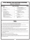
SECTION I
INTRODUCTION AND DESCRIPTION
1-1 Introduction
1-2 Description
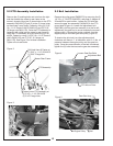
2-1 Preparation Of Mower
We are pleased to have you as a Bad Boy customer.
Your collection system has been designed to give you a
low maintenance, simple, and effective way to collect the
grass clippings from your mower. This manual is
provided to give you the necessary instructions to
properly mount and operate the collection system on
your mower. Please read this manual thoroughly.
Understand what each control is for and how to use it.
Observe all safety decal precautions on the machine and
noted throughout the manual.
All references made to right, left, front, rear, top
or bottom are as viewed from the normal operator’s
position on the mower.
The collection system is designed for turf maintenance
where there is a need to collect the grass clippings as
the mower cuts the turf. It is also good for picking up
leaves and twigs in pre-season and post-season clean-
up.
The blower, mounted on the right side of the unit, uses a
belt and gearbox system from the engine PTO shaft.
Drive train protection comes through belt slippage. The
blower draws grass clippings from the discharge area of
the cutter deck back to the 3 - 3.3 cubic foot collection
bags P#(G0002) at the rear portion of the mower frame.
The operator can engage the blower with a push of the
over-center linkage on the right side of the unit. Once the
bags are full with clippings, they can be released to
make for easy dumping.
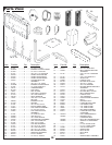
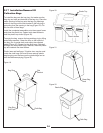
Carefully dismantle shipping box from around the
components. Cut retaining straps and separate the
parts. The collection system will have various parts
located inside. Remove and sort all parts for easy
identification.
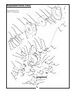
Before each step of assembly it will help to
study the exploded drawings on pages 8,9 and 10.
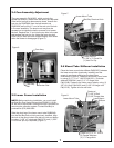
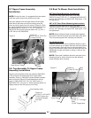
From the underside of the mower engine remove the bolt
and bushing from the electric clutch assembly. Replace
these parts with the engine pulley assembly P#(A0611),
lock washer, and bolt. See the listing below for
information on what hardware will need to be used and
added for the various types of mower engine options:
NOTE:
NOTE:
Section II
INSTALLATION FOR USE
23HP, 32HP Vanguard & 26HP Briggs ELS
26HP Kawasaki
27HP & 30HP Kohler
- Add
(2) flat washers P#(K0131) between clutch and pump
pulley, use (1) 7/16”-20 x 4” HHCS P#(K0359) and (1)
7/16” lock washer P#(K0053) to fasten engine pulley
assembly.
- Add (1) flat washer P#(K0131)
between clutch and pump pulley (has 2 existing washers
between clutch and pump pulley), use (1) M10-1.5 x
90MM HHCS P#(K0117) and (1) 7/16” lock washer
P#(K0053) to fasten engine pulley assembly.
- Do not add washer (has 1
existing washer between clutch and pump pulley), use
(1) 7/16”-20 x 4” HHCS P#(K0359) and (1) 7/16” lock
washer P#(K0053) to fasten engine pulley assembly.
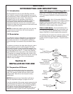
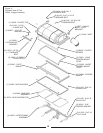
The added pulley will power the collection system. Note
that the center of the hub that is extended should be
upward toward the engine (Figure 1). Torque the bolt to
55 ft./lbs.
Figure 1.
Pump Pulley
Spacer (Existing)
Pump
Pulley
(Existing)
See Above For
Quantity Of
Spacers To Add To
Existing Spacers
Electric
Clutch
(Existing)
Engine
Pulley
Assembly
7/16” Lock
Washer
See Above For
Bolt Type