


GB - 24
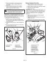
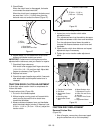
2. Tip the unit up onto front housing on a level
surface.
3. Remove lockpins from wheel axles and remove
wheels.
4. Remove two bolts from top of bottom cover.
5. Loosen two bottom screws and slide cover off.
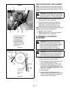
6. Disconnect pivot pin from the speed selector arm.
Save the hardware for reinstallation.
7. Carefully tap two roll pins out of center and right
end of hex shaft.
8. Remove four nuts from bearing cap on left side of
unit. Remove bearing and outside bearing cap.
9. Reinstall one nut to keep the inside bearing cap
in place.
10. Remove bearing cap/bushing and washer from
right side of unit.
11. Reinstall nuts on screws through side frame to
keep screws in place.
12. Slide friction disc assembly and hex shaft to the
right until the left end of shaft is clear of left
bearing. Tap lightly if necessary, to loosen. The
shaft slides out of the small pinion gear and
washer.
13. Carefully lift shaft and friction disc out of unit. As
you remove the assembly, the washers between
the bearing and sliding forks will be loose. Do not
lose the washers.
Replace Friction Disc
1. Remove three hex bolts and nuts holding friction
disc to shift carrier.
2. Remove the old friction disc. Put the new friction
disc in place, flat side to the shift carrier.
3. Reinstall the three bolts and nuts into the new
friction disc and hub. Torque to 5-6 lbf-ft (6.8 to
8.13 N•m).
Reinstall Friction Disc
1. Reinstall the shift carrier, the small pinion gear
and washer onto the hex shaft. The washer goes
between the bearing and the pinion gear.
2. Slide the shaft and attached parts into the frame,
through the right side hole first, then the left.
Pinion gear must mesh with the large gear.
3. Reinstall the flange bearing and washers into the
shift forks. Be sure the washers are inside the
forks.
4. Reinstall the bearing and outside bearing cap on
the left side of the frame.
5. On the right side of the frame, place the washer
on the end of the shaft.
6. Reinstall the bearing cap/bushing on the right
side of frame.
7. Reinstall roll pins in shaft. Be sure pins are
centered in shaft.
8. Connect the pivot pin to the speed selector arm
with the hardware removed in step 6 of Remove
Friction Disc on page 23.
9. Reinstall tires with lockpins.
10. Install bottom cover.
11. Set unit upright.
12. Connect spark plug wire to spark plug.
CAUTION: Before tipping unit, remove
enough fuel so that no spills occur.
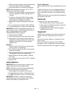
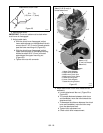
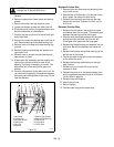
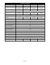
1. Hex Shaft
2. Friction Disc
3.Hex Bolts & Nuts
4. Shift Carrier
5.Roll Pins
6. Washers
7. Bearing Cap Screws
8. Bearing Cap/Bushing
9.Clutch Fork
10.Large Gear
11.Pinion Gear
1
2
3
4
5
6
9
11
10
8
7
OS2002
Figure 30
5
6
6