


GB - 23
5. Check Brake
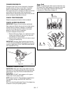
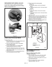
When the clutch lever is disengaged, the brake
must contact the attachment belt.
When the clutch lever is engaged, the brake must
be more than 1/16 in. (1.6 mm) away from the
belt and must not contact the frame (Figure 27).
6. Repeat steps 3–5 until attachment clutch lever
distance and brake contact are correct.
IMPORTANT: If attachment clutch/brake cannot be
adjusted within tolerances, see your Dealer for repairs.
7. Check belt finger clearance.
With clutch lever engaged, belt fingers should be
1/16–1/8 in. (1.6 - 3.0 mm) from belt. Adjust belt
fingers as necessary. See Figure 24.
8. Replace belt cover.
9. Check that auger/impeller stops within 3 seconds
after attachment clutch/impeller brake lever is
released.
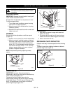
TRACTION DRIVE CLUTCH ADJUSTMENT
If drive slips, adjust traction clutch to compensate for
friction disc wear.
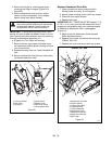
To test traction clutch (Figure 28):
1. Put unit in first forward speed.
2. Without engine running, push unit forward while
slowly moving the traction drive clutch lever
toward the handlebar.
3. Measure distance between lever and handlebar
when the wheels begin to brake. If distance is not
5-3/4 in. - 6-1/4 in. (14.6 cm - 15.9 cm), adjust the
traction clutch.
To adjust traction clutch (Figure 29):
1. Loosen jam nut on traction clutch cable
adjustment barrel.
Turn adjustment barrel up the cable to decrease
the distance between clutch lever and handlebar.
Turn the adjustment barrel down the cable to
increase the distance between clutch lever and
handlebar.
2. Check traction clutch lever distance and repeat
adjustment steps if necessary.
3. Tighten jam nut on traction cable adjustment
barrel.
FRICTION DISC REPLACEMENT
Remove Friction Disc
(Figure 30):
1. Shut off engine, remove key, disconnect spark
plug wire and allow unit to cool completely.
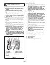
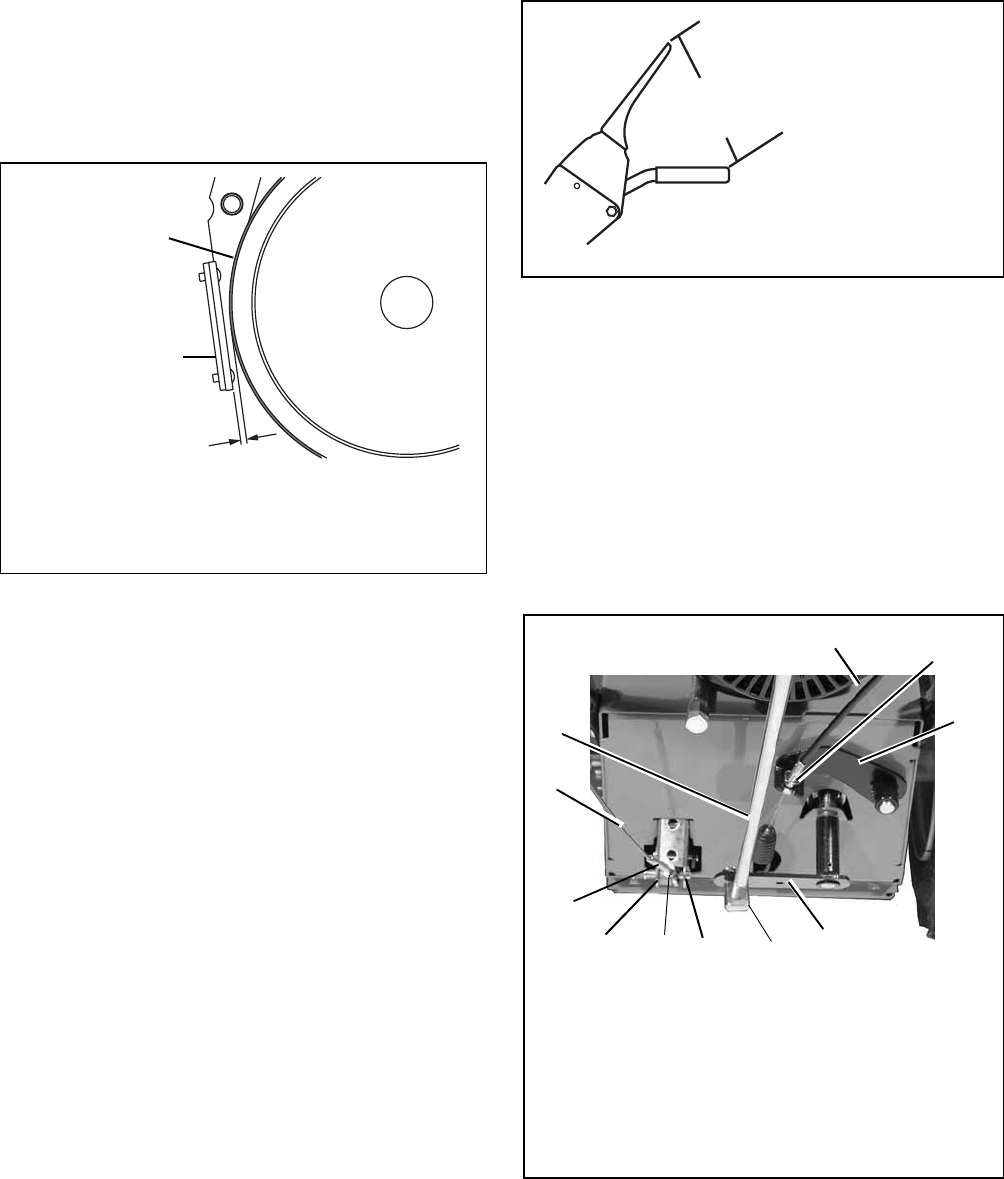
Figure 27
1.Drive Brake
2.Brake Shoe and Pad
1
2
1/16 in.
(1.6 mm)
OS2030
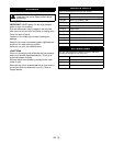
Traction Clutch Lever
OS2490
Figure 28
5-3/4 in. - 6-1/4 in.
(14.6 cm - 15.9 cm)
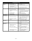
Figure 29
1.Traction Clutch Cable
2.Shift Rod
3.Attachment Control
Cable
4.Mounting Nuts
5.Attachment Clutch
Arm
6. Speed Selector Arm
7.Adjustment Pivot Pin
8.Cotter Pin and Clevis
9. Jam Nut
10.Traction Drive Clutch
Arm
11.Adjustment Barrel
OS7265
1
2
3
4
5
6
8
10
11
7
9