GB - 25
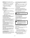
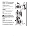
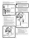
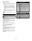
If chute does not rotate freely:
Tighten the cable by loosening the upper adjustment
nut, and then tightening the lower adjustment nut
against the bracket (Figure 27).
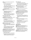
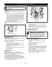
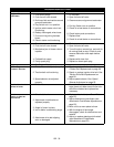
SPEED SELECTOR ADJUSTMENT
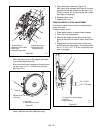
To adjust (Figure 28):
1. Place unit into service position.
2. Disconnect adjustment pivot pin from speed
selector lever.
3. Place the speed selector in the fastest forward
speed position.
4. Turn the speed selector lever straight down
towards the ground as far as it will go.
5. Thread the adjustment pivot pin along the shift
rod until it aligns with the mating hole on the
speed selector lever. Insert the pivot pin into hole.
6. Secure adjustment pivot pin with hairpin.
7. Make sure the speed selector shifts into each
speed position.
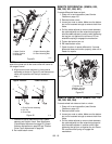
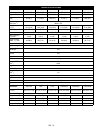
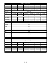
ATTACHMENT CLUTCH/BRAKE ADJUSTMENT
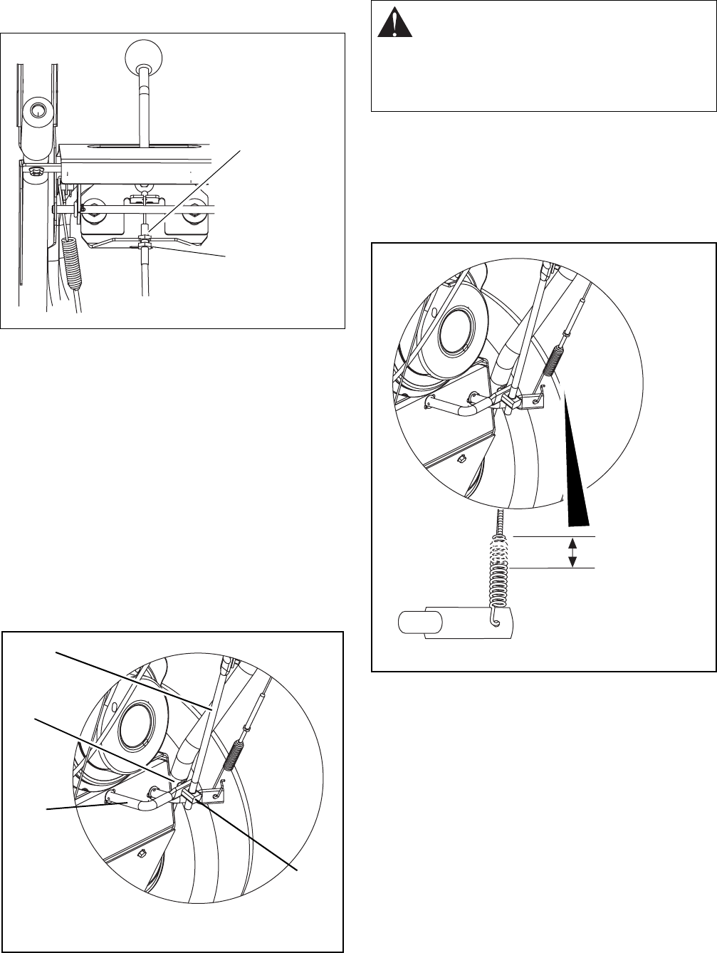
(Figures 29, 30 and 31)
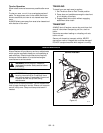
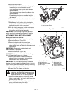
1. Measure spring extension.
a. Measure the length of the clutch cable spring.
b. While holding the attachment clutch lever
against the handlebar, measure the length of
the spring again. The spring should be
1/2-11/16 in. (12.7-17.5 mm) longer when the
lever is engaged.
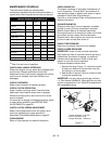
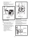
2. Reposition the idler on the attachment belt idler
arm to adjust the spring extension, if necessary.
a. Remove belt cover and loosen idler
adjustment nut.
b. To increase spring extension, move idler
closer to the engine sheave.
c. To decrease spring extension, move idler
farther from the engine sheave.
d. Tighten the idler adjustment nut.
NOTE: Moving the idler approximately 1/8 in. (3 mm)
will change the spring extension approximately 1/8 in.
(3 mm).
Loosen upper
adjustment nut.
Tighten lower
adjustment nut.
Figure 27
OS7180
Figure 28
1.Shift Rod
2.Adjustment Pivot Pin
3.Speed Selector Lever
4.Hairpin
2
3
1
4
OS7185
IMPORTANT: IMPROPER ADJUSTMENT
could result in unexpected movement of
auger and impeller causing death or serious
injury. Auger / impeller must stop within 5
seconds when Attachment Clutch/Impeller
Brake lever is released.
Figure 29
1/2 -11/16 in.
(12.7-17.5 mm)
OS7185
OS7190


