


7 - 22
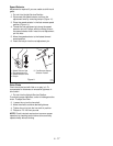
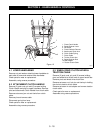
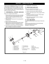
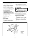
The unit can be equipped with either of two drive axles.
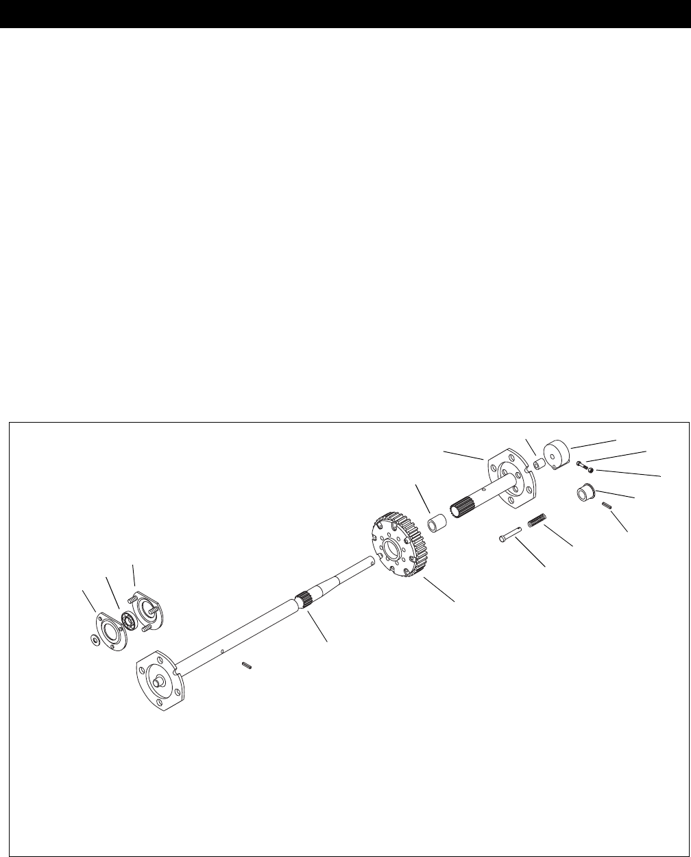
The first type is a differential axle (Figure 14). To lock
into two wheel drive the left hand wheel has a lockout
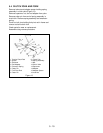
hub. The second type is a spur gear drive (Figure 15).
To lock a wheel to the axle, a pin is inserted through the
wheel hub and through the axle.
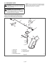
7.1 DIFFERENTIAL, LOCKOUT, AND AXLE
Place unit in Upright Service Position.
1. Remove groove pin that secures lockout assembly
to left hand axle and lockout assembly from shaft
(Figure 14). (Pin is tapered and must be driven
from small end.)
2. Remove roll pin that secures knob, spring and pin
to lockout hub.
3. Remove left hand axle from unit.
4. Remove roll pin from right hand axle, then remove
differential from axle while sliding axle from unit.
(Differential is serviced as a complete assembly.)
5. Check left hand axle bushings and other parts for
wear or damage and replace as necessary.
6. Reassemble in reverse order.
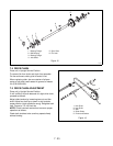
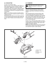
7.2 SPUR GEAR AND AXLE
Place unit in Upright Service Position.
1. Remove lockout pins and wheels (Figure 15).
2. Remove retaining rings outside of bearings.
3. Remove retaining ring next to the spur gear toward
the center.
4. Pull axle out toward the right side. The spur gear
should slide off the axle and key.
5. Check bearings and gear for wear or damage.
Replace as necessary.
7.3 AXLE BEARINGS
To remove axle bearings, remove axles per instructions
above.
Remove cap screws and lock nut that hold bearing
retainer and bearing on the frame.
Assemble in reverse order.
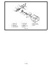
SECTION 7 - REDUCTION DRIVE
1. Bearing Flange
2. Ball Bearing
3. Bearing Flange
4. Right Hand Axle
5. Left Hand Axle
6. Sleeve Bushing
7. Sleeve Bushing
8. Pin
9. Compression Spring
10.Lockout Hub
11.Knob
12.Groove Pin
13.Differential Assembly
14.Lock Nut
15.Cap Screw
PS0611
Figure 14
1
2
3
4
5
6
7
8
9
10
11
13
14
15
12