


4 - 14
IMPORTANT:
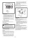
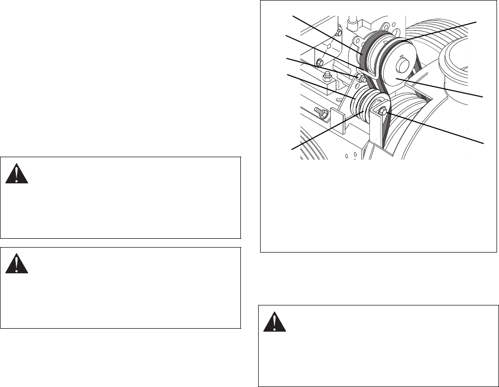
Use care when rotating the belt fingers
to prevent deformation of parts.
NOTE:
To gain clearance engage traction clutch and if
necessary pull back attachment idler arm clevis pin.
3. Replace traction drive belt and belt fingers in
reverse order making sure pulleys align. If
alignment is necessary, loosen engine pulley set
screws, reposition pulley and retighten set screws.
Check alignment of attachment driven pulley and
align if necessary.
4. Check and adjust clutch.
4.9 ATTACHMENT DRIVE BELT
To Replace the Attachment Drive Belt:
1. Place unit in the Belt Service Position.
2. Remove the belt. It may be necessary to hold the
brake open.
3. If pulley alignment is necessary, loosen pulley set
screws. Reposition pulley and retighten set screws.
4. Replace chute crank and secure with hair pin.
Replace belt guard cover and secure with screws.
5. Check and adjust clutch.
4.10 SHEAR BOLTS
IMPORTANT:
Use only Ariens Shear Bolts for
replacement. Use of any other type of shear bolt may
result in severe damage to the unit.
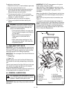
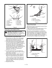
Occasionally a foreign object may enter the auger/
impeller housing and jam the auger, breaking Shear
Bolts which secure the auger to the shaft (Figure 6).
This allows auger to turn freely on the shaft preventing
damage to the gear drive.
WARNING:
IMPROPER ADJUSTMENT
could result in death or serious injury.
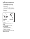
IMPELLER BRAKE MUST DISENGAGE
when clutch is engaged. Brake must be at
least 1/16" (1.6 mm) to 1/8" (3.2 mm)
minimum from belt when disengaged.
WARNING:
ROTATING PARTS can cut or
amputate body parts. Keep hands and feet
away.
Loose clothing, long hair or scarves can get
caught in rotating parts and cause death or
serious injury.
WARNING:
ROTATING PARTS can cut or
amputate body parts. Keep hands and feet
away.
Loose clothing, long hair or scarves can get
caught in rotating parts and cause death or
serious injury.
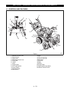
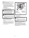
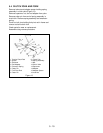
OS0601
1. Traction Belt Idler
2. Cap Screw
3. Belt Finger
4. Traction Drive Belt
5. Attachment Belt Idler
6. Attachment Drive Belt
7. Engine Pulleys
8. Attachment Idler
Adjustment Hardware
2
3
4
5
Figure 5
1
7
6
8