


GB - 11
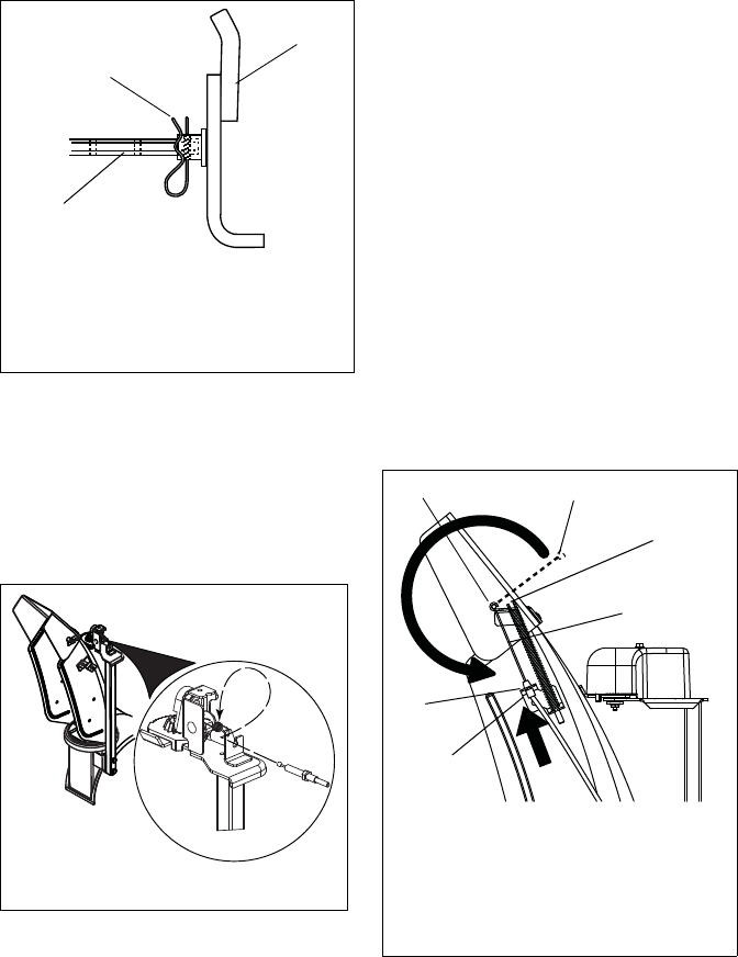
NOTE: After the chute rod has been inserted
through the hex hole in the control assembly,
placing the unit in the service position (see
Service Position on page 23) will ease
alignment and installation of the hair pin.
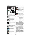
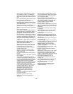
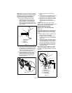
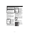
8. Secure the chute rod to the control
assembly with the hair pin removed in
step 6 using the end hole location as
shown in Figure 11. Insert the hairpin
with the loop end to the left of the chute
rod so the control assembly follows a full
range of travel.
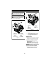
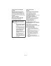
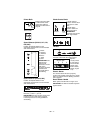
9. Connect the chute lock cable to the lock
arm by fitting the cable ball end into the
slot on the lock arm and then insert the
chute lock cable fitting into the bracket
on the chute pedestal (Figure 12).
10. Adjust and tighten jam nuts on cable to
remove cable slack. Be sure not to
pretension lock arm so it retracts from
the gear teeth see Discharge Chute
Control on page 27.
11. Replace the gear cover removed in
step 4.
12. Orient the chute and pedestal to its most
vertical position and tighten pedestal
hardware to 15 – 31 lbf-ft (20 – 42 N•m).
13. Make sure the discharge chute rotates
left and right when you push the
discharge chute control lever left and
right.
NOTE: If chute does not stay in position,
adjust as directed in Discharge Chute Control
on page 27, or repair before operation.
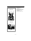
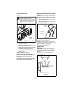
Remote Deflector Control
(921013, 017, 018, 020, 022, 023)
(Figure 13)
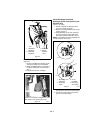
Connect the cable end to the cable anchor on
the discharge deflector before clipping the
cable to the cable bracket on the discharge
chute.
1. Route deflector remote cable along the
left side of the chute pedestal.
2. Insert the barrel on the cable end into
the bracket on left side of chute deflector
(Figure 13).
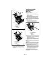
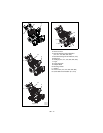
3. Hold seal out of the way while routing
the cable through the bracket on the left
side of the discharge chute, and then
push the cable fitting into the bracket.
4. Push the seal securely over the end of
the cable fitting to prevent water from
entering the cable.
Check deflector travel. Adjust nut on cable
end under handlebar to obtain full travel, if
necessary (see Remote Deflector Control on
page 27).
.
Figure 11
1. Chute Control
Assembly
2. Hairpin
3. Chute Rod
1
2
3
OS7157
Figure 12
OS7271
Figure 13
1. Cable Anchor
2. Cable End
3. Deflector Cable
4. Cable Fitting
5. Cable Bracket
1
2
3
5
4
3
OS7070