


GB - 24
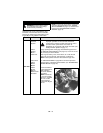
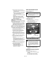
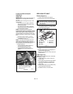
Forward and Reverse Speed
Adjustment
(Figure 20)
IMPORTANT: The unit should track within 2
feet (0.61 m) of a straight line for 30 feet
(9.14 m).
The travel of the steering levers may need
adjustment if:
• The unit turns to the right or left when
both steering levers are pushed as far
forward as possible.
• The unit turns to the right or left when
both steering levers are pulled back as
far rearward as possible.
NOTE: The side the unit turns toward
indicates that the wheel on that side is turning
slower than the other wheel. Either the wheel
that is turning faster needs to slow down or
the wheel that is turning slower needs to be
sped up to allow the unit to travel in a straight
line.
1. Determine which way the unit turns.
2. Tip seat forward (see TIPPING SEAT
FORWARD on page 17).
NOTE: The forward travel adjustment bolt
adjusts the forward travel of the steering
lever. The rear travel adjustment bolt adjusts
the rearward travel of the steering lever.
3. Adjust speed by:
• Turning adjustment bolt clockwise to
decrease steering lever travel.
• Turning adjustment bolt counter
clockwise to increase steering lever
travel.
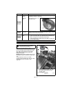
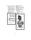
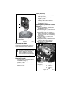
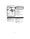
REPLACING PTO BELT
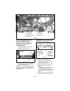
Remove (Figure 21)
1. Lower mower deck to the ground.
2. Remove belt covers from mower deck.
3. Hook a puller into idler hole and pull idler
arm towards outside of unit until tension
is removed from PTO belt.
4. Remove PTO belt from left mower deck
pulley.
5. Slowly release idler arm until tension is
removed from idler spring.
6. Remove PTO belt from mower deck and
electric clutch.
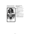
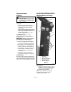
Install (Figure 21)
NOTE: Do not install PTO belt on left mower
deck pulley in step 1.
1. Install PTO belt on electric clutch and
mower deck.
2. Hook a puller into idler hole and pull idler
arm towards outside of unit until PTO
belt can be routed around left mower
deck pulley.
3. Slowly release idler arm until idler pulley
rests firmly against PTO belt.
4. Install belt covers on mower deck.
OE0330
Figure 20
3
2
1
1. Forward Travel Adjustment Bolt
2. Rear Travel Adjustment Bolt
3. Steering Lever
CAUTION: Use care when releasing
idler spring tension. Keep body parts
well away from idler when performing
this operation.
Figure 21
7
OE0080
3
1. Idler Spring
2. Electric Clutch
3. PTO Belt
4. Idler Hole
5. Idler Pulley
6. Idler Arm
7. Belt Cover
1
2
4
6
5