GB - 12
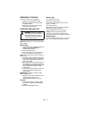
CUTTING HEIGHT ADJUSTMENT
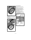
Front Wheel
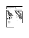
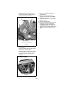
Remove the lock pin from the left front wheel
and then remove the wheels and axle from
the unit. Install the wheels and axle at the
desired cutting height, and then secure them
in place with the lock pin.
DANGER: Avoid injury from
rotating blade.
ALWAYS shut off engine before
adjusting cutting height.
CAUTION: Both rear wheels must
be set at same height or traction
drive may not work properly.
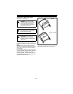
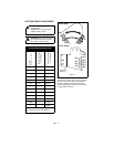
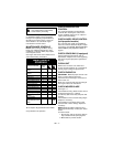
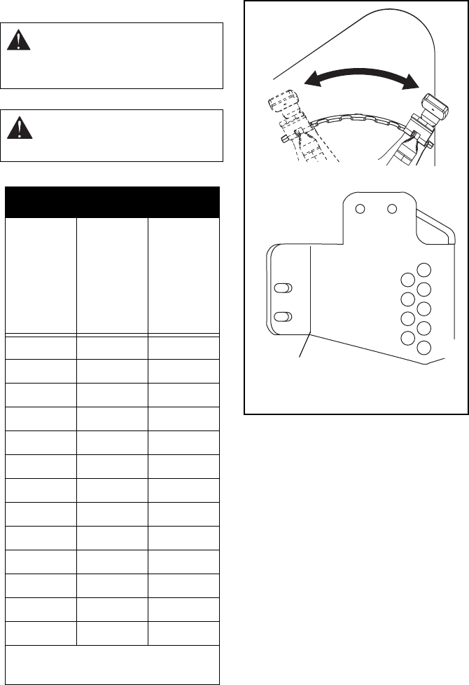
Cutting Height Settings Chart
Cutting
Height – in. (cm)
Adjuster in Shortest
Cutting Range
Adjuster in Tallest
Cutting Range
1P1/H1
1-1/4 P2/H2
1-1/2 P3/H2
1-3/4 P3/H3
2P4/H4P1/H4
2-1/4 P5/H4 P2/H4
2-1/2 P5/H5 P2/H5
2-3/4 P6/H6 P3/H6
3P4/H6
3-1/4 P4/H7
3-1/2 P4/H8
3-3/4 P5/H8
4P6/H9
P = Position of the Cutting Height Lever
H = Hole in the Front Axle Bracket
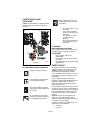
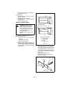
Figure 8
H8
H6
H4
H2
H1
H3
H5
H7
Front Axle
Bracket
H9
P1
P6
Rear Wheel
Front Wheel


