4 - 25
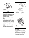
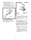
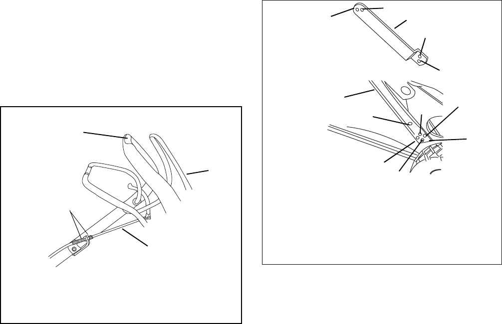
To check the control cable spring:
1. Squeeze the wheel drive control bail towards the
handlebar until the spring starts to open.
2. Measure the distance between the wheel drive bail
to the handlebar indentation.
3. To obtain the proper adjustments turn the control
cable nuts at the handlebar or the bottom of the
control cable anchor against the anchor supports.
4.10 HANDLEBAR ADJUSTMENT
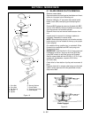
Holes in handlebar braces provide four height
positions, a service position, and a storage position
(except on professional models).
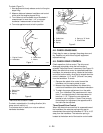
Use one of the four holes to adjust handlebar height to
a safe, comfortable position. Place bolt on handlebar
bracket through one of holes 1, 2, 3 or 4 in order of
increasing height (See Figure 11).
NOTE:
On Professional models nuts and bolts replace
pins.
For storage, rotate handlebar forward and place pins
through holes further up braces.
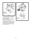
4.11 SPEED CONTROL BELL CRANK
The speed control bell crank holds the speed selector
rod in position after a speed has been set. The spring
washers may become loose with normal wear. If the
speed selector rod does not stay firmly in position,
adjust the speed control bell crank. See Figure 12.
To adjust:
1. Remove cover, fully compress the helical spring
lockwashers with lock nut and then back lock nut
off, one half turn.
2. If the speed selector rod is still too loose, tighten
lock nut by small increments until it holds its
position. Tightening the lock nut too much will not
allow the speed selector rod to move at all.
3. Align notch in left hand side of cover with bolt and
secure with knob.
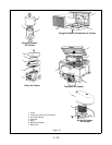
Figure 10
1. Traction Cable
2. Handlebar
Indentation
3. Cable Nuts
4. Wheel Drive Control
1
2
3
4
Figure 11
1. Hole No. 1
2. Hole No. 2
3. Hole No. 3
4. Hole No. 4
5. Handlebar Stud
6. Handlebar Adjustment
Link
7. Professional Bracket
8. Storage Position
OM0271
1
2
3
4
5
6
8
1
2
3
4
7


