4 - 24
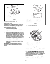
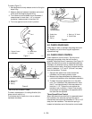
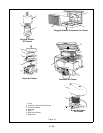
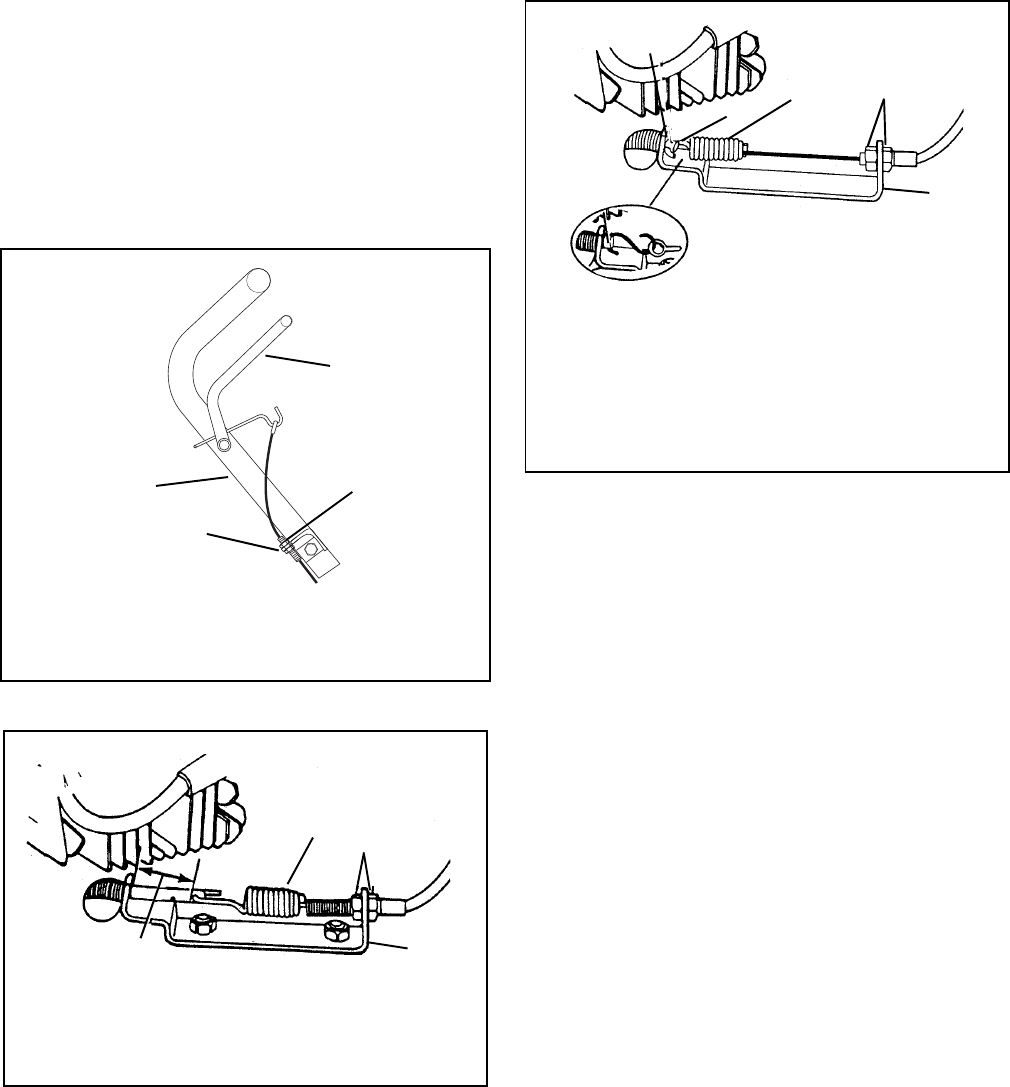
To check (Figure 7):
1. Start engine and slowly release control until engine
stops firing.
2. Measure distance between handlebar and control
at the point that engine stopped firing.
3. Turn cable nuts at handlebar mount clockwise if
measurement is more than 1-1/4" or counter-
clockwise if measurement is less than 3/4".
4. Turn nuts against mount to lock in position.
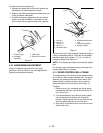
There must not be slack in cable.
To check, rotate blade in it’s cutting direction (this
draws control rod fully in).
To eliminate slack in cable, turn nuts on cable at
handlebar clockwise.
4.8 CHECK GRASS BAG
Check bag for wear or damage. Keep bag clean and
dry. Replace only with Ariens original equipment
replacement bag.
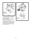
4.9 CHECK DRIVE CONTROL
Check operation of drive control. The drive must
disengage completely when the bail handle is
released. Adjust bail travel if necessary. See Figure 10.
When the wheel drive control is squeezed toward the
handlebar, the extension spring, located at the bottom
end of the traction cable, must start to extend when the
control is between 1-1/2" and 2" (3.8 and 5 cm) away
from the handlebar. To check:
1. Squeeze the wheel drive control toward the
handlebar until the spring starts to open.
2. Measure the distance between the wheel drive
control and handlebar at the handlebar indentation.
3. To obtain the proper adjustment, turn the cable
nuts. Turn clockwise if the measurement is more
than 2"; counterclockwise if the measurement is
less than 1-1/2". Tighten the nuts against the
bracket to lock in position. If there is not enough
thread length for adjustment, the opposite end of
the cable can be adjusted.
Three Speed Drive Control
When the wheel drive control bail is squeezed toward
the handlebar, the extension spring must start to
extend when the control bail is between 3-7/8" to 4-1/8"
away from the handlebar. The extension spring is
located at the bottom end of the traction control cable.
Figure 7
1. Engine Control
2. Handlebar
3. Cable Nuts
4. Mount
OM0280
1
2
3
4
Figure 8
1. Cable Nuts
2. Bracket
3. Spring
1-1/8" to 1-5/16"
1
2
3
Figure 9
1. Cable Nuts
2. Bracket
3. Spring
4. Spring or "S" Hook
5. Control Rod
1
2
3
4
5
S Hook on
Some Models


