


10 - 29
10.1 ALUMINUM GEAR CASE
1. Remove auger/impeller and gear case from
housing referring to
Auger/Impeller
Section.
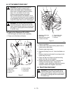
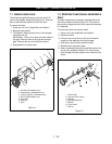
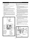
2. Remove six bolts that hold right and left gear case
halves together (Figure 23).
3. If flange bushings need replacement, first remove
seals from outside of gearcase halves with a
screwdriver. Flange bushings can then be pressed
out from outside in with a bearing driver. Bushings
are very lightly pressed in.
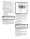
4. When replacing bushings make sure the flat on the
flange of bushing fits in the inside notch of the
case.
5. There are two special washers, one on either side
of bronze gear. If burred or worn they should be
replaced.
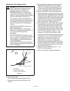
6. Holding bronze gear on rake shaft is a groove pin.
When driving out, drive in direction of least
resistance. the flat on bronze gear face will fill the
hole in the side of the gearcase.
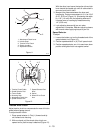
7. Remove bronze bushing from front of worm shaft
by sliding it off. Replace if necessary. Notice that a
flat on the bushing flange positions the bearing
inside the gearcase.
8. Behind rear bronze bushing is a seal which fits into
a groove in gearcase. It should be replaced at time
of repair.
9. Rear bushing is a larger diameter than one in front,
but are identical in design. Replace if necessary.
10.If replacement of thrust collar is necessary, again
drive out groove pin towards direction of least
resistance.
11.Inspect worm for burrs or black coloration. If either
show up, replace shaft.
12.For re-assembly, replace the gasket with P/N
00031700 (use Loctite 518 provided). Make sure
the flats on the bushings are in their proper place.
This case requires Ariens L-2 P/N 00008000 and
should be half full.
After assembly is complete you should be able to turn
input shaft freely.
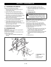
Auger/impeller gearcase is lubricated with Ariens L-2
(P/N 00008000). Check lubrication by removing filler
plug. Lubrication should be even with hole with unit
sitting level. It may be necessary to insert a wire into
the hole to check level. Unit will not be damaged by
over-lubricating.
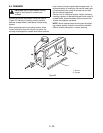
SECTION 10 - GEAR CASE
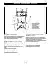
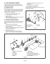
Figure 23
PS0281
1. Impeller
2. Worm Shaft and Gear Assembly
3. Thrush Collar
4. Case, Left Side, Large Bore
5. Case, Right Side, Small Bore
6. Rake Shaft
7. Seal
1
2
3
4
5
6
7