


4 - 16
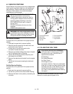
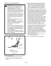
To Replace the Traction Drive Belt
1. Place unit in the Belt Service Position.
2. Pull idler away from belt (Figure 6) and remove belt
from idler pulley, engine and drive pulley (it may be
necessary to turn engine pulley using rewind
starter).
3. Rotate belt fingers out and away from belt and
pulley by removing one cap screw and loosening
the other.
IMPORTANT:
Use care when rotating the belt fingers
to prevent deformation of parts.
NOTE:
To gain clearance engage traction clutch and if
necessary pull back attachment idler arm clevis pin.
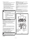
4. Replace traction drive belt and belt fingers in
reverse order making sure pulleys align. If
alignment is necessary, loosen engine pulley set
screws, reposition pulley and retighten set screws.
Check alignment of attachment driven pulley and
align if necessary.
5. Check and adjust clutch.
4.10 SHEAR BOLTS
IMPORTANT:
Use only Ariens Shear Bolts for
replacement. Use of any other type of shear bolt may
result in severe damage to the unit.
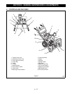
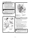
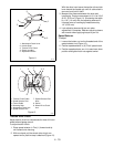
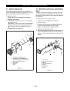
Occasionally a foreign object may enter the auger/
impeller housing and jam the auger, breaking shear
bolts which secure the auger to the shaft (Figure 7).
This allows auger to turn freely on the shaft preventing
damage to the gear drive.
For Replacement:
1. Slide auger outward against roll pin and align hole
in shaft with hole in auger. The holes in the shaft
for the roll pins and shear bolts line up.
2. Drive shear bolt through hole (if shear bolt was
broken this will drive the remaining part from shaft).
3. Secure shear bolt with nut.
4. The shear bolts should not be overtightened to
collapse the auger center tube to the auger drive
shaft.
4.11 TIRE PRESSURE
Maintain the unit tire pressure at a maximum of
20 PSI (138 kPa).
4.12 ADJUSTMENTS
Discharge Chute Deflector
To adjust the drag force, loosen or tighten the two bolts
to accomplish the desired drag.
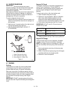
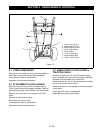
Discharge Chute
If chute does not stay in position while operating,
tighten nut on carriage bolt at pivot point to increase
tension on spring (Figure 9).
Smooth and easy rotation of properly lubricated chute
with crank (without binding) is obtained by adjusting
pinion and flat gear teeth so they mesh together.
Adjust, using adjustment slots in pinion bracket which
is secured to chute strap.
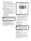
WARNING:
ROTATING PARTS can cut or
amputate body parts. Keep hands and feet
away. Loose clothing, long hair or scarves can
get caught in rotating parts and cause death
or serious injury.
WARNING:
ACCIDENTAL ENGINE START
UP can cause death or serious injury.
ALWAYS stop engine, remove key, wait for
moving parts to stop and remove wire from
spark plug before adjusting or servicing.
OS0401
1. Auger
2. Roll Pin
3. Shear Bolt(s)
4. Nut(s)
2
3
4
Figure 7
1