


4-14
Section 4 OPERATING INSTRUCTIONS
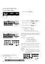
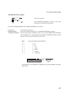
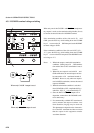
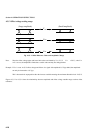
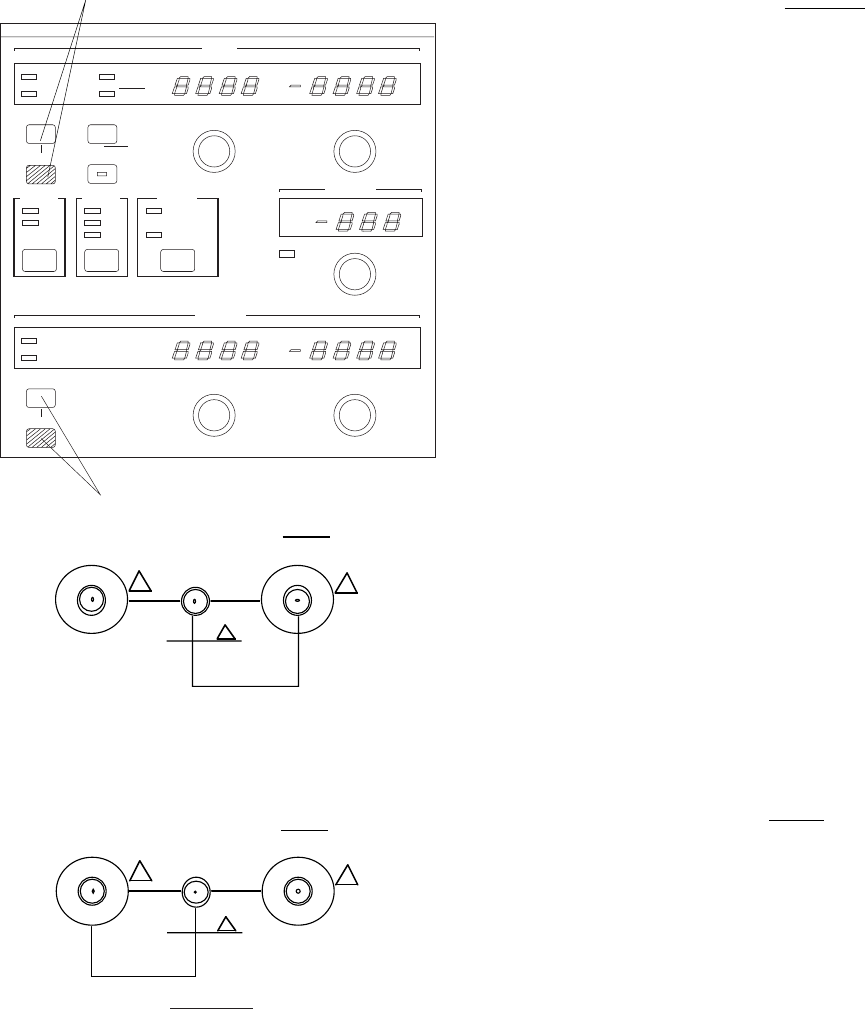
4.3.1 DUMMY terminal voltage switching
When only one of the CLOCK 1 and CLOCK 1 complemen-
tary outputs is used, use the attached semirigid cable (10 cm)
to connect the unused side to the DUMMY terminal.
If the termination condition of the side used is 50 , and
GND, press the ECL key while holding down the GUARD
key of to turn on the 50 GND lamp and set the DUMMY
terminal voltage to GND.
If the termination condition of the side used is ECL (50 ,
-2 V), press the ECL key while holding down the GUARD
key of to turn on the ECL lamp and set the DUMMY termi-
nal voltage to -2 V.
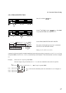
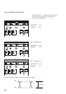
Notes: 1. When both outputs, match their termination
conditions. (Setting one to 50 , GND termina-
tion and the other to ECL termination is not al-
lowed.)
2. When only one output is used with 50 , and
GND termination, the unused output can also
be connected to a 50 terminator instead of
DUMMY. However, only when one output is
used with ECL termination, connect the unused
output to DUMMY.
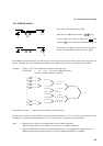
3. When the termination condition is switched
from 50 Ω GND to ECL, amplitude 0.8Vp-p
and offset -0.9V (V
OH
) are automatically set.
4. Since the DATA and DATA outputs are in
dependent, connection to the DUMMY termi-
nal is unnecessary.
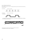
5. If a commercially available ECL terminator is
used to measure the output waveform, wave
form distortion (ringing) may be observed.
This phenomenon depends on the characteris-
tics of the ECL terminator and does not mean
that the output of this equipment contains
waveform distortion.
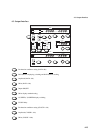
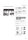
When only CLOCK 1 output is used
OUTPUT
ps
DELAY TIME
BUSY
CLOCK 1
50 GND
ECL
AMPLITUDE
Vp - p
OFFSET
V
ECL
GUARD
ECL DISPLAY
DATA/DATA
TRACKING
GUARD
OUTPUT
ON
OFF
OFFSET
V
OH
V
TH
V
OL
DISPLAY
1/1 SPEED
1/4 SPEED
(OPTION.03)
DATA
50 GND
ECL
DATA
DATA
AMPLITUDE
Vp - p
OFFSET
V
CLOCK 1
When only CLOCK 1 output is used