4-5
Change the BIT value with the button below the LED. When
LOGIC is positive, lighting of the LED indicates high level.
Used the PRESET ALL or PAGE key when changing DATA
collectively.
PAGE 0 or 1
All BITs of the displayed PAGE are set to 0 or
1.
ALL 0 or 1
Pressing this key while holding down the
GUARD key sets all BITs specified by
DATA LENGTH to 0 or 1.
Next, set in pattern B (turn on the B LED) and set pattern
B in the same way as pattern A.
However, do not change DATA LENGTH here because it is
shared by A and B. If DATA LENGTH is changed here,
DATA LENGTH of pattern A is also changed.
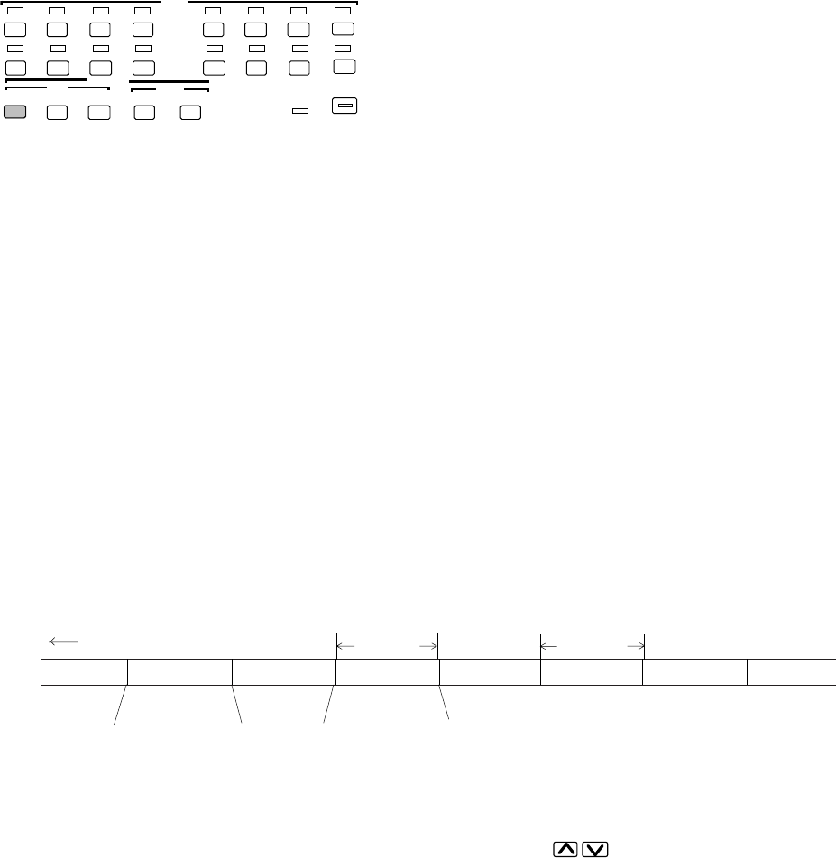
Two patterns, A and B, can be set, and repetition times can be set for each pattern. The data lengths are the same for both
patterns.
The following are examples of 128bit patterns:
Pattern A: 0 0 0 ••• 1 1 1 Repetition time: 2
Pattern B: 1 0 1 ••• 0 1 0Repetition time: 3
Output
Pattern A Pattern A Pattern B Pattern B Pattern B Pattern A Pattern A Pattern B
0 0 0 ••• 1 1 1 1 0 1 ••• 0 1 0
Bit 1 of page is set to the head of the pattern.
Note: The FUNCTION switch on the rear of the instrument can be set to switch between patterns A and B by an external
signal. In this case, the A/B LOOP TIME display is turned off and the keys of are disabled.
In addition, A/B switch-timing bit sift is performed using SW5 and SW6. (See Section 4.6.)
4.2 Generation Pattern Setting
128 bits
128 bits


