


1-3
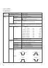
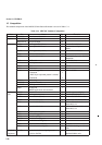
1.2 Specifications
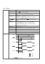
CLOCK1/CLOCK1, CLOCK2 3 systems
Error
insertion
Error ratio
1 10 (n = 4 , 5, 6, 7 , 8 , 9)
Insertion
position
Insertion possible at any one of 32 channels
(Rear panel swith)
Error insertion by rising edge of external signal input
Insertion
position
Insertion possible at any one of 32 channels
(Rear panel switch)
DISABLE
function
Error insertion when external signal input level is “H”
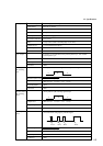
1 10
Insertion
position
Insertion possible at any one of 32 channels
(Rear panel switch)
DATA is set to “0” while external signal input level is “L”.
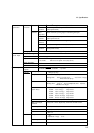
External
Clock Input
0.05 12.5 GHz
0.4 to 2.5 Vp-p
0.05 to 0.5 GHz : Square wave only
> 0.5 GHz: Sine wave or square wave (duty 50 %)
50 Ω
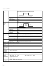
Internal
External
Eror
injection
Error ratio
Gating input
Frequency range
Input level
Input waveform
Input impedance
Connector
SMA
Clock output
Number of
outputs
Pattern
generation
-n
-n
(n = 4 , 5, 6, 7 , 8 , 9)
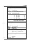
CLOCK1
/ CLOCK1
CLOCK2
500 ps/1 ps step
Amplitude 0.25 to 2.0 Vp-p/Step 2 mV
Setting error: 15% (1.5 to 2.0 Vp-p), % (0.5 to 1.5 Vp-p),
Offset
-2.0 to 2.0 V (V ) /Step 1 mV
Setting error: 15 % or 15 % of Amplitude, and 100 mV,
Rise/fall times
(10%–90%)
8 GHz 1.5 to 2 Vp-p 35 ps or less
8 GHz 1.5 to 2 Vp-p 50 ps or less
8 GHz 1.0 to 1.5 Vp-p 40 ps or less
8 GHz 1.0 to 1.5 Vp-p 55 ps or less
8 GHz 0.25 to 1.0 Vp-p 45 ps or less
8 GHz 0.25 to 1.0 Vp-p 60 ps or less
15 % or less or 150 mV, whichever is larger
Duty ratio adjust
function
Duty ratio can be adjusted by semifixed variable resistor
50 Ω (with back termination)
APC-3.5
V :
Amplitude: 1 Vp-p 35 %
50 Ω (without back termination)
SMA
Waveform distortion
Load impedance
Connector
Delay range
Connector
Load impedance
Output level
OH
OH
or single
or single
mV(0.25 to 0.5 Vp-p)
0 200 mV
whichever is larger
50 Ω /GND, 50 Ω/–2 VTermination