


754323-100 Rev A
13
INSTALLATION AND FRAMING INSTRUCTIONS:
The variety of installations possible for this combination system may require framing procedures
other than those shown. Locate studs as required. Ensure roughing-in dimensions are proper,
plumb and square. Provisions must be made in all installations for an access opening for servicing
the air blower and controls. It is strongly recommended that an additional opening be provided for
access to the drain components. The apron should not be used as the primary access opening.
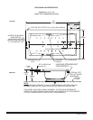
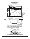
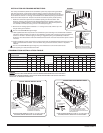
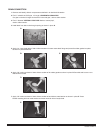
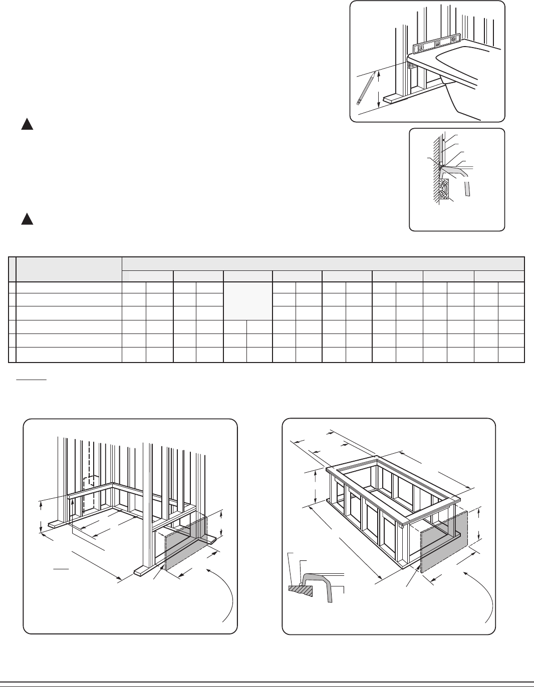
1. Position the combination system into the installation opening and level the deck in both
directions, shimming the integral feet with attached baseboard as necessary. Refer to the
Combination Installation Table for nominal installation dimensions. Mark the final position of
the underside of the deck by tracing a line on to the studs (see Figure 1).
2. Remove the air massage system and attach a 1 x 4 stringer to the studs, with the top of the
stringer touching the traced line.
The rim of the bath must not support weight.
TYPICAL PIER TYPE INSTALLATION
AS DESIRED
F
CUTOUT
AS DESIRED
E
CUTOUT
D
24
(610 mm)
12
(305 mm)
MOUNTING
SURFACE
WATERPROOF
SEALANT
BATH
TYPICAL RECESS INSTALLATION
24
(610 mm)
12
(305 mm)
D
A
B
C
LEVELING
STRINGERS
TILE
TILE
BEAD
STRIP
LEVELING STRINGER
1 x 4 (not for support)
BATH
ADHESIVE
SEALANT
WALLBOARD
NOTE: Tile bead kit not included
and must be purchased separately.
D
TYPICAL
INSTALLATION
FIGURE 1
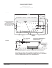
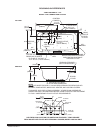
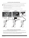
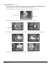
3. Install supplied cable drain components to the combination system according to the enclosed drain installation
instructions. Before replacing your bath for final installation, be certain that an opening has been provided in the
sub-floor for the drain. See the roughing-in drawing for suggested opening size (shadowed) and location
dimensions. The drain/overflow of the bath extends below the bottom of the bath. Note that this requires a cutout
in the floor.
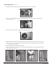
4. Replace combination system and re-shim the integral support feet with attached baseboard, shimming the entire
length of the baseboard as needed. Secure the shims using construction adhesive, silicone or equivalent
materials.
The rim of the bath must not support weight. Any finish material such as tile or wall board must be
self-supporting if it contacts the deck of the bath.
!
!
ACCESS PANEL MUST BE LOCATED
ON THE SAME SIDE AS THE MOTOR.
ALLOW OPEN FRAMING ON PUMP/MOTOR
END FOR SERVICE.
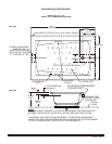
ACCESS PANEL MUST BE LOCATED
ON THE SAME SIDE AS THE BLOWER.
ALLOW OPEN FRAMING ON
BLOWER END FOR SERVICE.
UNLESS AN ACCESS OPENING OF AT LEAST 12" X 24" (305 X 610mm)
IS PROVIDED, WARRANTY SERVICE WILL NOT BE PERFORMED.
UNLESS AN ACCESS OPENING OF AT LEAST 12" X 24" (305 X 610mm)
IS PROVIDED, WARRANTY SERVICE WILL NOT BE PERFORMED.
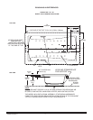
NOTE:
FRONT EDGE
OF BATH MUST
BE SUPPORTED
BY STUD WALL OR
AMERICAN STANDARD
APRON KIT
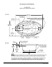
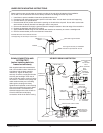
** USE CUTOUT TEMPLATE PROVIDED FOR 2709 MODEL
NOTICE:
DO NOT BUILD THE SURROUNDING STRUCTURE BEFORE RECEIVING YOUR AIR BATH.
STRUCTURE MEASUREMENTS SHOULD BE VERIFIED AGAINST THE ACTUAL AIR BATH
RECEIVED TO ENSURE PROPER FIT.
60-1/4"
35"
36"
19"
58-1/2"
34-1/2"
1530mm
889mm
914mm
483mm
1486mm
876mm
66-1/4"
35"
36"
19"
64-1/2"
34-1/2"
1683mm
889mm
914mm
483mm
1638mm
876mm
72-1/4"
35"
36"
19"
70-1/2"
34-1/2"
1835mm
889mm
914mm
483mm
1791mm
876mm
60"
40-3/4"
41-3/4"
19"
58-1/4"
40-1/4"
1524mm
1035mm
1060mm
483mm
1480mm
1022mm
72-1/4"
41"
42"
19"
70-1/2"
40-1/2"
1835mm
1041mm
1067mm
483mm
1791mm
1029mm
COMBINATION INSTALLATION TABLE
DIM.
DESCRIPTION
A
B
C
D
E
F
59-3/4"
39-3/4"
41-3/4"
21"
58"
40-1/8"
1518mm
1511mm
1060mm
533mm
1473mm
1019mm
Nominal tub length recess opening
Nominal tub apron support opening
Nominal tub width recess opening
Nominal tub height opening
Nominal tub length cutout
Nominal tub width cutout
71-3/4"
39-3/4"
41-3/4"
20"
70"
40-1/4"
1823mm
1511mm
1060mm
508mm
1778mm
1022mm
19-1/2"
67"
36-1/2"
495mm
1702mm
927mm
**
2748 2742
COMBINATION MODEL NUMBER
2709
3571
3572 3573 3574 3575