


ASSEMBLY
SHD 03/09 Assembly Section 3-4
© 2009 Alamo Group Inc.
ASSEMBLY
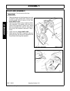
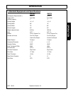
GEARBOX AND EXTENSION SHAFT ASSEMBLY
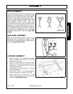
For forward rotation attach the outboard bearing
plate (item 1) on the left side of cutter housing with
(2) 3/8” x 7/8” bolts, and (3) 3/8” locknuts. The third
nut is used at the rear mounting hole (item2). This
bolt is used as an anchor for the idler arm spring.
For reverse rotation attach the outboard bearing on
the right side of the cutter housing with (2) 3/8” x 7/
8” bolts and (3) 3/8” locknuts. The third nut is used
at the front mounting hole. This bolt is used as an
anchor for the idler arm spring.
Remove existing nuts and lockwashers (item 3)
from bearing housing.
NOTE: On forward rotation units, remove only the
lower two fasteners.
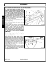
Position gearbox and extension shaft assembly
onto gearbox mounting frame (item 5). Attach
gearbox to frame by using only one gearbox
retaining bolt (5/8” x 1-1/2”) (item 6) through the
mount plate and into the gearbox housing. Do not
tighten this bolt at this time. It should have at least
1/4” free threads to move in and out. See Image
ASM-FL-0050.
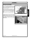
Secure bearing housing to outboard bearing plate
(item 1) using the bolts previously removed and
torque to proper tightness.
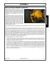
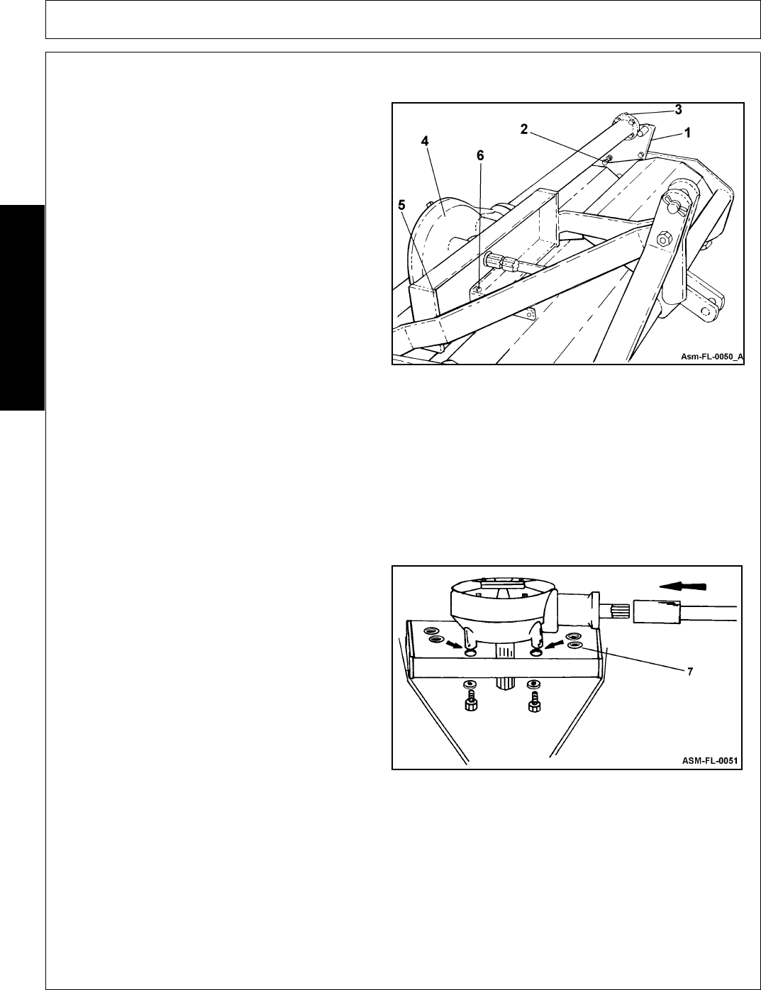
After completing the above steps, check the
distance between the gearbox mounting lugs and
the mount plate, if lugs do not rest on the mounting
plate evenly, insert shims from shim kit (#000552)
on each lug as necessary to insure that the gearbox
pulls up evenly on the mounting plate (see item 7).
Secure gearbox by using (2) 5/8” x 1-1/4” bolts for
upper gearbox fee and (2) 5/8” x 1-1/2” bolts for
lower feet. Torque to 170 ft-lbs.
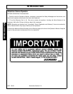
IMPORTANT: Failure to properly shim the gearbox
feet as necessary will result in improper alignment
and will cause premature wear on the gearbox,
bearing, extension shaft, or coupling.