


ASSEMBLY
PA91 03/09 Assembly Section 3-5
© 2009 Alamo Group Inc.
ASSEMBLY
DELIVERY
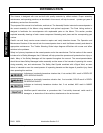
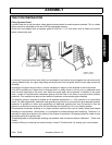
1. The machine is delivered in a partially dismantled condition. To make ready for attachment to the tractor it
will be necessary to select a hard level surface
2. Cut the banding straps and remove the attached articles.
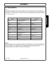
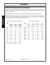
3. Fill the reservoir to capacity with oil selected from the chart on Section 3-9 to increase the stability of the
machine.
4. Remove and discard the transport strap connecting the flail head to the frame and also the lift ram stop
strapped to the rod.
ATTACHMENT TO TRACTOR
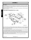
Si Model
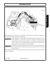
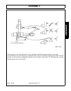
1. On Si model, drive the tractor up as closely as possible and connect the return and supply hoses to the
tractor. Fit suitable return connection to the tractor and connect the return hose before connecting the supply
hose to the tractors external services point with a suitable self seal coupling.
*With the aid of a crowbar prise the flail head sideways until there is sufficient clearance to allow the tractor to
be driven up and the draft links connected. Assistance will be needed to simultaneously select “Reach out” and
“Angle down” to allow the oil to flow while the arms are being moved.
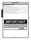
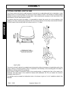
As a safety precaution, to prevent the possibility of the flail head slipping sideways and the
arm collapsing on the fitter as the head is pried sideways, a loop of strong rope or wire with
sufficient slack to allow the required flail head movement should connect the frame and
dipper. This will then act as a stopper in the event of this happening. Leave in position until
attachment is complete.
2. Swing up the linkage plate and fix securely in position with the nut and bolt provided.
3. Adjust tractor drop arms to enable the draft links to lower within 15 ins (375 MM.) of the ground.
4. Remove the top link and machine yoke completely.
5. Reverse the tractor squarely to the front of the machine, engage draft link pins and secure.
6. Attach yoke to the top hitch position on the tractor ensuring the lug for the top link is uppermost.
7. Unlimber the machine controls from its storage position and fit into the tractor cab.
8. Install the top link between the yoke and upper hitch position on the machine. If necessary, fit Cat I sleeves
into the ball ends of the top link.
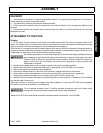
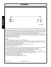
*Raise the machine on its three point linkage to the working height, i.e. when the PTO shaft and the gearbox
stub shaft are (as near as possible) in a straight line.
Do not operate quadrant lever of machine controls through the rear cab window while
standing on or amongst linkage components. Always seek assistance.
*Measure the PTO drive shaft length as shown in diagram below and subtract 1 inch (25 MM.).