


ASSEMBLY
260/272/284 01/11 Assembly Section 3-5
© 2011 Alamo Group Inc.
ASSEMBLY
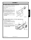
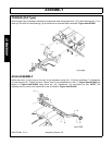
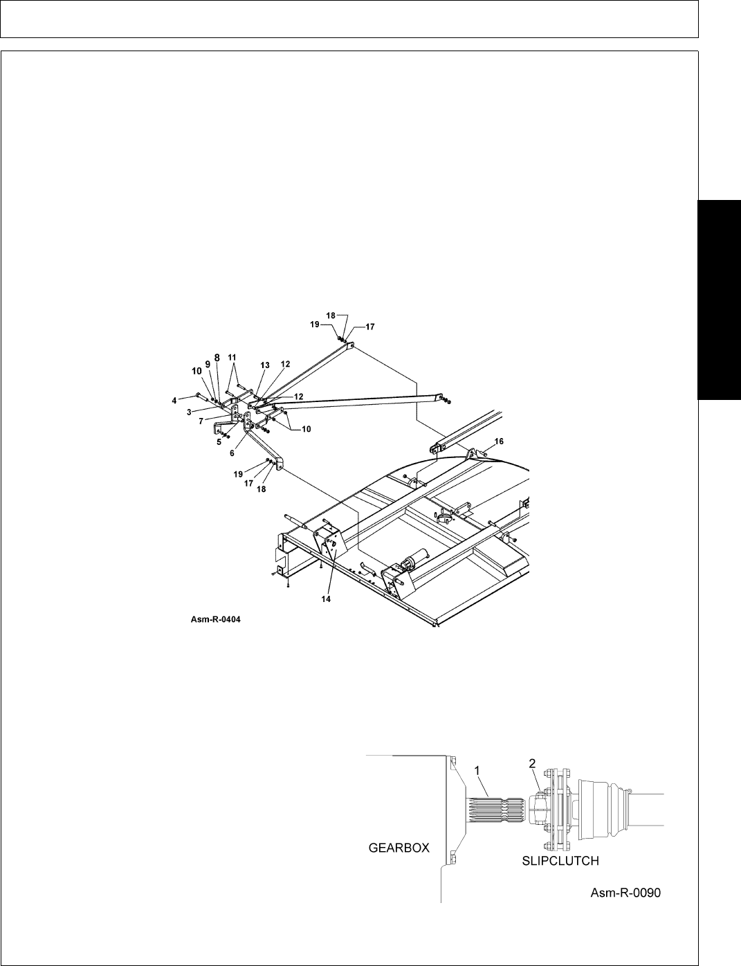
A-FRAME INSTALLATION (Model 284)
1. Attach the A-Frame Bars (2) to the right and left Hitch Lugs (14 & 15) with two 5/8” x 2” bolts (16), 5/8”
washers (17), bushing (18) and 5/8” locknuts (19).
2. Attach the Lift Strap Bars (1) to the Mainframe with two 5/8” bolts (16), 5/8” flatwasher (17), bushing (18)
and 5/8” locknut.
3. Attach flex links (3) to A-Frame bars (2) with 5/8” x 3” carriage bolts (7), bushings (8), flatwasher (9) and
nut (10).
4. Insert quick hitch bushing (5) between A-Frame and insert 5/8” x 4-1/2” bolt (4) and 3/4” locknut (6).
5. Insert 5/8” x 2-3/4 bolt (11) through center holes in flex links (3) with bushing (12) through forward holes in
rear braces (1).
6. Insert bolt (13) through 2nd hole from front in rear braces (1) and secure with locknut (10).
7. Insert 5/8” x 2-3/4” bolt (11) through rear holes in flex links (3) through bushing (12) with bushing over or on
top of rear braces (1). Figure Asm-R-0404
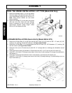
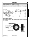
DRIVELINE ATTACHMENT
Before starting assembly, make certain that all paint, dirt, and grease are removed from gearbox shaft (1). To
ease assembly apply a light coat of grease to splines and assemble. Do not assemble a driveline without a
shield. Entanglement in rotating shafts can kill. Figure Asm-R-0090
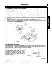
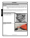
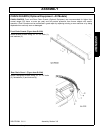
Attach slip clutch end of the driveline to the gearbox
input shaft securely. Make certain that the slip
clutch is fully onto the input shaft splines. Tighten
the locknuts (2) alternately until they have reached
the proper torque. Refer to Torque Chart in the
Maintenance Section.