


ASSEMBLY
260/272/284 01/11 Assembly Section 3-3
© 2011 Alamo Group Inc.
ASSEMBLY
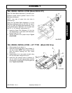
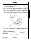
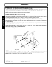
TAIL WHEEL INSTALLATION (Model 260 & 272)
Align Tail Wheel Beam Weldment (1) between pivot
brackets located behind gearbox mount on the
Mainframe Weldment.
NOTE: Long side of caster fork pivot tube is
positioned up.
Attach the Tail Wheel Beam Weldment (1) to the
Mainframe Weldment with one 5/8” Bolt (4), and 5/
8” nut (5). Slide Tail Wheel Beam Weldment (1) into
Gauge Wheel Mount Weldment (3) and retain with
two 1/2” x 1-1/2” bolts (6), and locknuts (7).
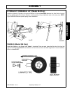
1. Insert the Caster Fork Weldment (11) into the
Tail Wheel Beam (1) and retain with Flatwasher
(9) and Cotter Pin (10).
2. Tighten all bolts to the proper torque. Figure
Asm-R-0408.
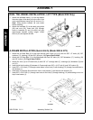
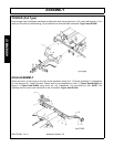
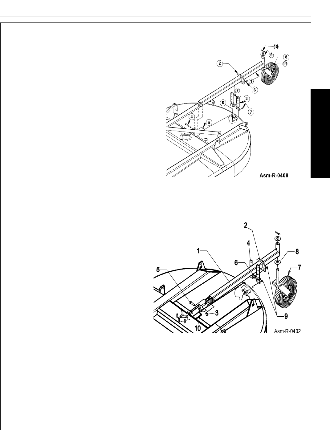
TAIL WHEEL INSTALLATION - LIFT TYPE (Model 284 Only)
1. Slide bracket (2) onto beam (1).
2. Insert bolt (28) through lugs on end of beam (1)
and lug on deck. NOTE: Insert spacer (10)into
deck lug before inserting bolt (28). Install
locknut (3).
3. Install bracket (4) to rear center of deck using
bolt (24) and retain using locknut (23).
4. Insert bolt (24) through holes in brackets (2)
and (4) which will give approximately desired
cutting height. Install locknut (23) and tighten all
bolts. Figure Asm-R-0402.