


7
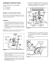
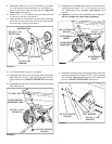
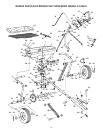
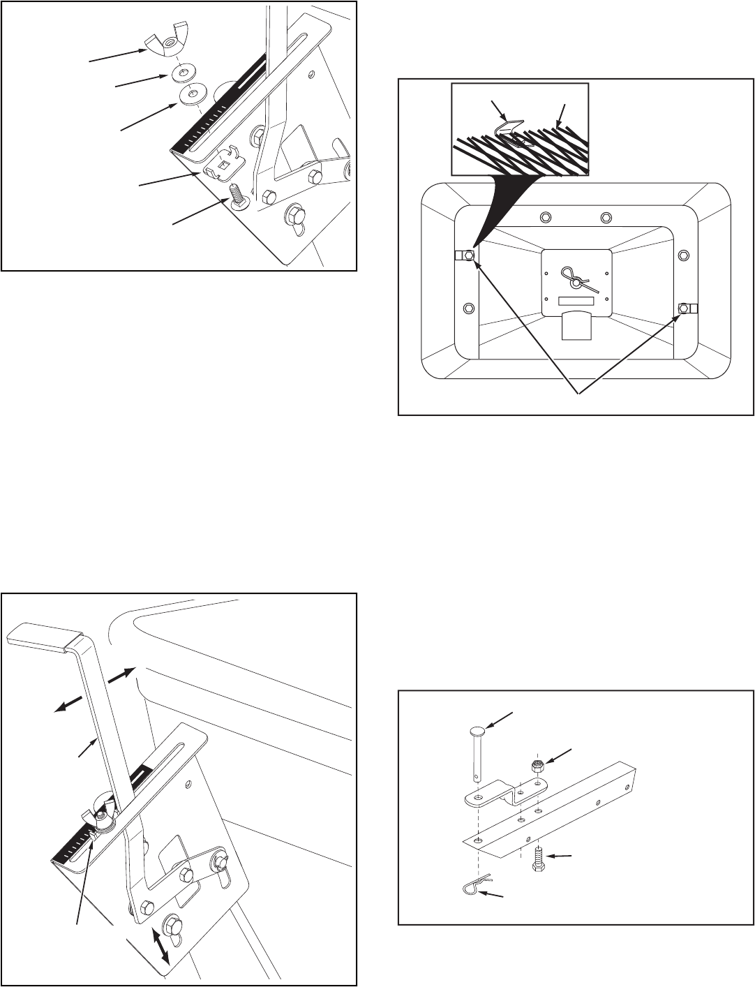
24. Position the fl ow control mounting bracket (fi gure 13).
a. Push on fl ow control arm until it locks in "OFF"
position.
b. Slide fl ow control mounting bracket along tube until
closure plate in bottom of hopper just closes.
c. Snug the 5/16" lock nuts just enough to hold fl ow
control mounting bracket in place.
d. Set adjustable stop at "5". Pull fl ow control arm
against stop. Verify that closure plate has opened
about half way.
e. If closure plate does not open half way, adjust
position of fl ow control mounting bracket until
closure plate will open about half way at "5" and
will still close when arm is locked in "OFF" position.
Tighten
the 5/16" lock nuts.
FIGURE 13
FIGURE 12
FLOW
CONTROL
ARM
OFF
ON
1
2
3
4
6
7
8
9
10
5
ADJUSTABLE
STOP (S)
(SETTING "5")
ON
OFF
(R) NYLON
WING NUT
OFF
ON
1
2
3
4
6
7
8
9
10
5
(K) 5/16" FLAT
WASHER
(J) NYLON
WASHER
(S) ADJUSTABLE
STOP
(F) 1/4" x 3/4"
CARRIAGE BOLT
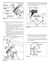
26. Assemble the hitch bracket to the hitch extension bracket
using two 3/8" x 3/4" hex bolts (D) and 3/8" nylock hex
nuts (I). Insert the bolts from the bottom. See fi gure 15.
27. Assemble the hitch pin (P) through the hitch bracket and
the hitch extension bracket and secure with the hair cotter
pin (O). See fi gure 15.
FIGURE 15
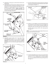
25. Place the screen down into the hopper, sliding the edge
of the screen under one of the clips. Slightly bow the
screen to slide the opposite side of the screen under
the other clip. See fi gure 14.
FIGURE 14
CLIPS
CLIP
SCREEN
(D) 3/8" x 3/4"
HEX BOLT
(I) 3/8" NYLOCK
HEX NUT
(P) HITCH PIN
(O) 1/8" HAIR
COTTER PIN