


4
ASSEMBLY INSTRUCTIONS
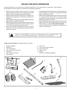
TOOLS REQUIRED FOR ASSEMBLY
(1) Pliers
(2) 7/16" Wrenches
(2) 1/2" Wrenches
(2) 9/16" Wrenches
REMOVAL OF PARTS FROM CARTON
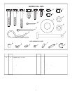
Remove all parts and hardware packages from the carton.
Lay out all parts and hardware and identify using the
illustrations on pages 2 and 3.
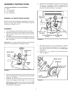
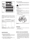
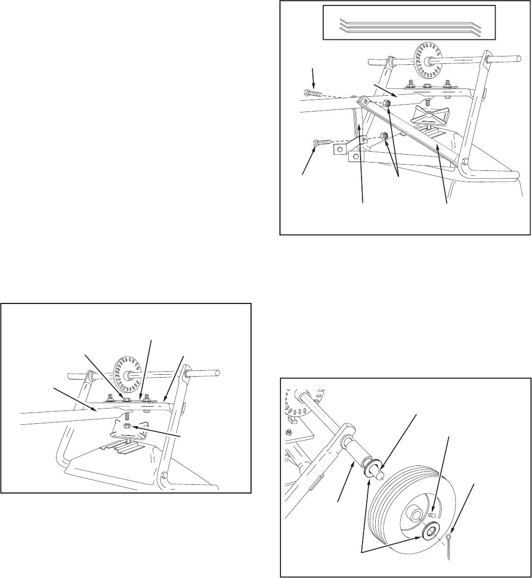
FIGURE 1
FIGURE 2
FIGURE 3
CROSSOVER
TUBE
HITCH
TUBE
SHAFT
SUPPORT
PLATE
MIDDLE
LOCK
NUT
MIDDLE BOLT
(C) 1/4" x 2"
HEX BOLT
(B) 1/4" x 1-3/4"
HEX BOLT
(G) 1/4" NYLOCK
HEX NUT
(2) HITCH BRACES
OUTER
HITCH
TUBE
(2) HITCH BRACES
OUTER
STACK HITCH BRACES AS SHOWN
SMALL HOLE
(Q) SPACER
(L) 3/4"
FLAT WASHER
(N) 1/8" x 1-1/2"
COTTER PIN
AIR VALVE
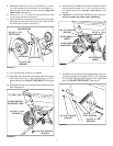
1. Turn the spreader upside down as shown in fi gure 1.
2. Remove the lock nut from the middle bolt in the crossover
tube and shaft support plate. Leave the bolt in place.
See fi gure 1.
3. Assemble the hitch tube onto the middle bolt and secure it
with the same lock nut you removed.
DO NOT TIGHTEN
YET.
See fi gure 1.
IMPORTANT:
The hitch tube must attach to the side of the
crossover tube opposite the shaft support plate.
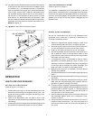
ASSEMBLY
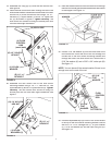
4. Stack the hitch braces into two sets of three, making
sure the raised sides of the braces are facing the same
direction. See fi gure 2.
5. Assemble the six hitch braces (three per side) to the
inside of the hopper frame using a 1/4" x 1-3/4" hex
bolt (B) and 1/4" nylock hex nut (G) on each side.
DO
NOT TIGHTEN YET.
The hitch braces should be able
to move freely. See fi gure 2.
7. Assemble a spacer (Q), a 3/4" fl at washer (L), a wheel
(air valve facing out) and another 3/4" fl at washer (L)
onto the end of the axle that has only the
small hole
.
See fi gure 3.
8. Install a 1/8" x 1-1/2" cotter pin (N) into the hole in the
axle. See fi gure 3.
6. Assemble the four
outer
hitch braces to the hitch tube
using a 1/4" x 2" hex bolt (C) and a 1/4" nylock hex nut
(G).
DO NOT TIGHTEN YET.
Do not assemble the two
inner hitch braces at this time. See fi gure 2.