


5
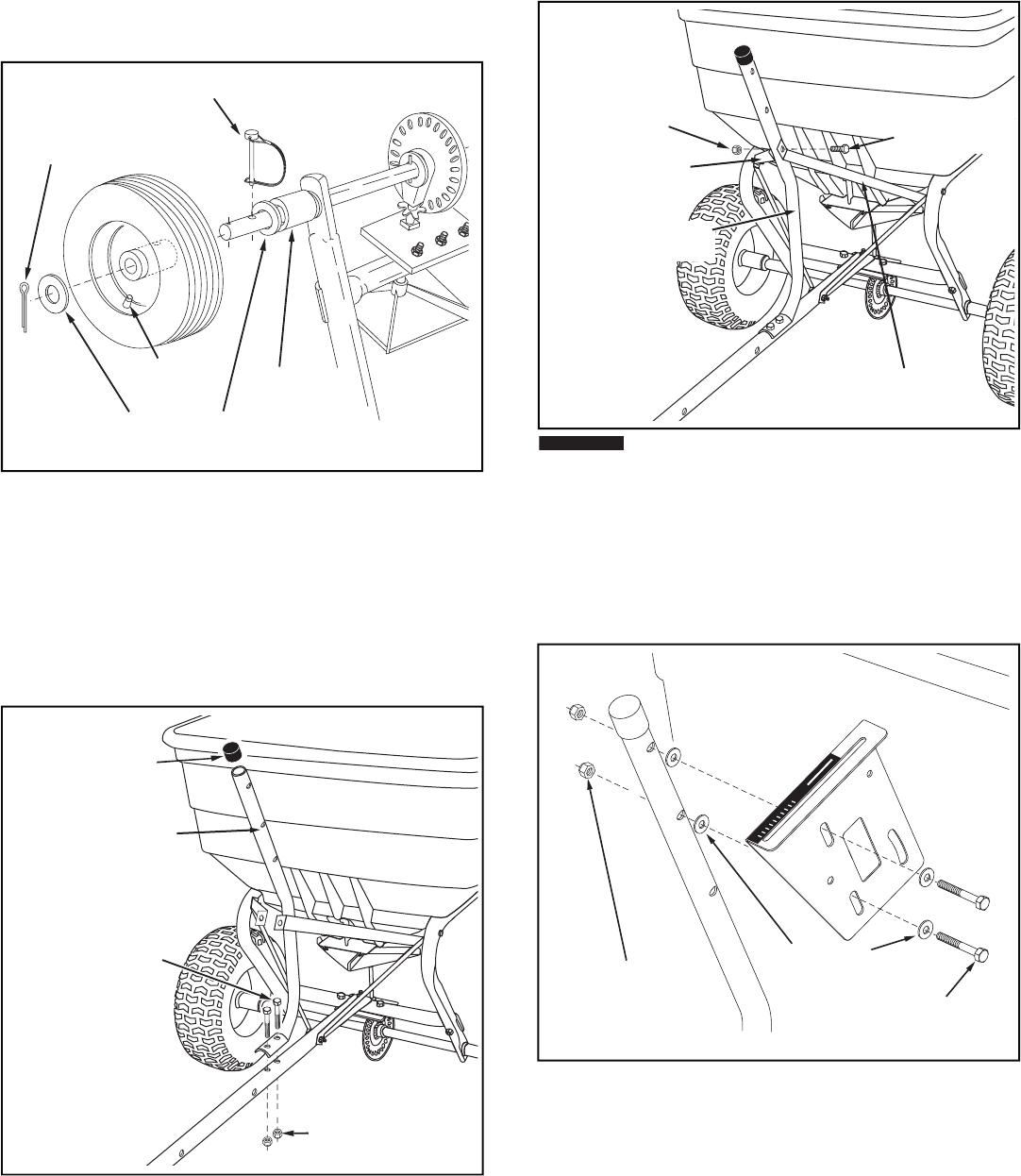
FIGURE 4
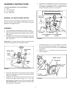
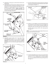
12. Turn the spreader upright on its wheels.
13. Assemble the fl ow control mounting tube to the hitch
tube using two 5/16" x 1-3/4" hex bolts (A) and 5/16"
nylock hex nuts (H).
DO NOT TIGHTEN YET.
See fi gure
5.
14. Assemble the vinyl cap (T) onto the fl ow control mounting
tube. See fi gure 5.
FIGURE 5
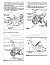
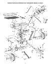
9. Assemble a spacer (Q), a 3/4" fl at washer (L), a wheel
(air valve facing out) and another 3/4" fl at washer (L)
onto the end of the axle that has both the
large and
small holes
. See fi gure 4.
10. Install a 1/8" x 1-1/2" cotter pin (N) into the small hole
in the end of the axle. See fi gure 4.
11. Open the bail on the drive pin (W) and install it through
the wheel and the large hole in the axle. Close the bail
to lock the pin in place. See fi gure 4.
FIGURE 7
(H) 5/16" NYLOCK
HEX NUT
(A) 5/16" x 1-3/4"
HEX BOLT
(K) 5/16"
FLAT WASHER
OFF
ON
1
2
3
4
6
7
8
9
10
5
(W) DRIVE PIN
AIR VALVE
(Q) SPACER
(L) 3/4" FLAT
WASHER
(N) 1/8" x 1-1/2"
COTTER PIN
FIGURE 6
(B) 1/4" x 1-3/4"
HEX BOLT
(G) 1/4" NYLOCK
HEX NUT
HITCH BRACE
INNER
FLOW CONTROL
MOUNTING TUBE
HITCH BRACE
INNER
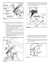
15. Assemble the two
inner
hitch braces to the fl ow control
mounting tube using a 1/4" x 1-3/4" hex bolt (B) and a
1/4" nylock hex nut (G).
DO NOT TIGHTEN YET.
See
fi gure 6.
16.
Tighten
all nuts and bolts assembled up to this point.
Do not collapse the tubes when tightening.
17. Assemble the fl ow control mounting bracket to the fl ow
control mounting tube using two 5/16" x 1-3/4" hex bolts
(A), four 5/16" fl at washers (K) and two 5/16" nylock hex
nuts (H).
DO NOT TIGHTEN YET.
See fi gure 7.
(A) 5/16" x 1-3/4"
HEX BOLT
(H) 5/16" NYLOCK
HEX NUT
(T) VINYL CAP
FLOW CONTROL
MOUNTING TUBE