


6
FIGURE 9
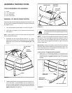
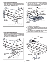
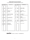
14. Place the screen down into the hopper.
DO NOT
place
it under the clips in bottom of hopper at this time. See
fi gure 9.
15. Place the motor assembly down into the hopper, inserting
the end of the spreader shaft into the impeller coupler.
Secure it with a 1/8" x 1-1/4" cotter pin, spreading the
ends of the pin around the coupler. See fi gure 9.
16. Fasten the motor mount bracket to the hopper using four
5/16" x 1" hex bolts, 5/16" fl at washers, nylon washers
and 5/16" nylock nuts. See fi gure 9.
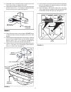
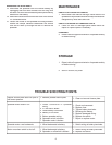
12. Assemble a seal (turned as shown in fi gure 8) onto the
motor shaft. Slide it up against the motor.
13. Assemble the impeller coupler onto the motor shaft and
secure it with a 1/8" x 1-1/4" cotter pin. Spread the ends
of the pin around the coupler. See fi gure 8.
5/16" x 1"
HEX BOLT
NYLON
WASHER
5/16" NYLOCK NUT
MOTOR
ASSEMBLY
5/16" FLAT
WASHER
SCREEN
1/8" x 1-1/4"
COTTER PIN
SPREADER
SHAFT
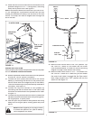
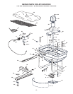
17. Lift the screen up and slide the seal down the spreader
shaft to rest against the plastic bushing in the bottom
of the hopper. See fi gure 10.
18. Slide one edge of the screen under one of the clips.
Then, slightly bow the screen to slide the opposite side
of the screen under the other clip. See fi gure 10.
FIGURE 10
CLIPS
CLIP
SCREEN
SHAFT
SEAL
BUSHING
1/8" x 1-1/4"
COTTER PIN
SEAL
IMPELLER
COUPLER
FIGURE 8