


4
ASSEMBLY INSTRUCTIONS
TOOLS REQUIRED FOR ASSEMBLY
(1) Pliers
(2) 7/16" Wrenches
(2) 1/2" Wrenches
(2) 9/16" Wrenches
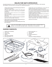
REMOVAL OF PARTS FROM CARTON
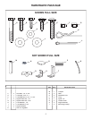
Remove all parts and hardware packages from the carton. Lay
out all parts and hardware and identify using the illustrations
on pages 2 and 3.
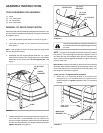
FIGURE 1
FIGURE 2
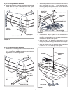
1. Turn the spreader upside down as shown in fi gure 1.
2. Press the two plugs into the ends of the frame tube.
See fi gure 1.
HINT:
Use a block of wood to help press the plug down
into the end of the tubing.
3. Assemble the two angle brackets and two 1/4" nylock
nuts onto the ends of the longer bolts that are already
assemble to the frame tube.
Do not tighten yet.
See
fi gure 1.
4. Fasten the defl ector to the angle brackets using two 1/4"
x 3/4" hex bolts, 1/4" fl at washers and 1/4" nylock nuts.
Allow the angle brackets to swivel so that the defl ector
curves naturally between the angle brackets and then
tighten all nuts
. See fi gure 2.
1/4" NYLOCK
NUT
1/4" FLAT
WASHER
1/4" x 3/4"
HEX BOLT
DEFLECTOR
ANGLE
BRACKET
1/4" NYLOCK
NUT
PLUG
5/16" x 1-2"
HEX BOLT
5/16" NYLOCK NUT
MOUNTING
BRACKET, R.H.
FIGURE 3
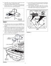
NOTE:
The top of the hopper should be at least 30" above
the ground. The mounting holes shown in fi gures 3 and 4
will make the top of the hopper even with the vehicle's rear
rack. If exhaust blows against spreader, a higher mounting
position may help.
Position the spreader for adequate clearance if
the vehicle muffl er discharges straight toward
the rear.
IMPORTANT:
Before proceeding, determine if the mounting
brackets, when attached directly to the spreader frame, will
fi t onto the vehicle rack. If they need to be farther apart, use
the extension brackets in fi gure 4.
If you are NOT using extension brackets:
5. Attach the R.H. mounting bracket to the frame tube
using two 5/16" x 2" hex bolts and 5/16" nylock nuts as
shown in fi gure 3.
Tighten.
Repeat for the L.H. mounting
bracket.