4
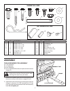
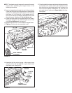
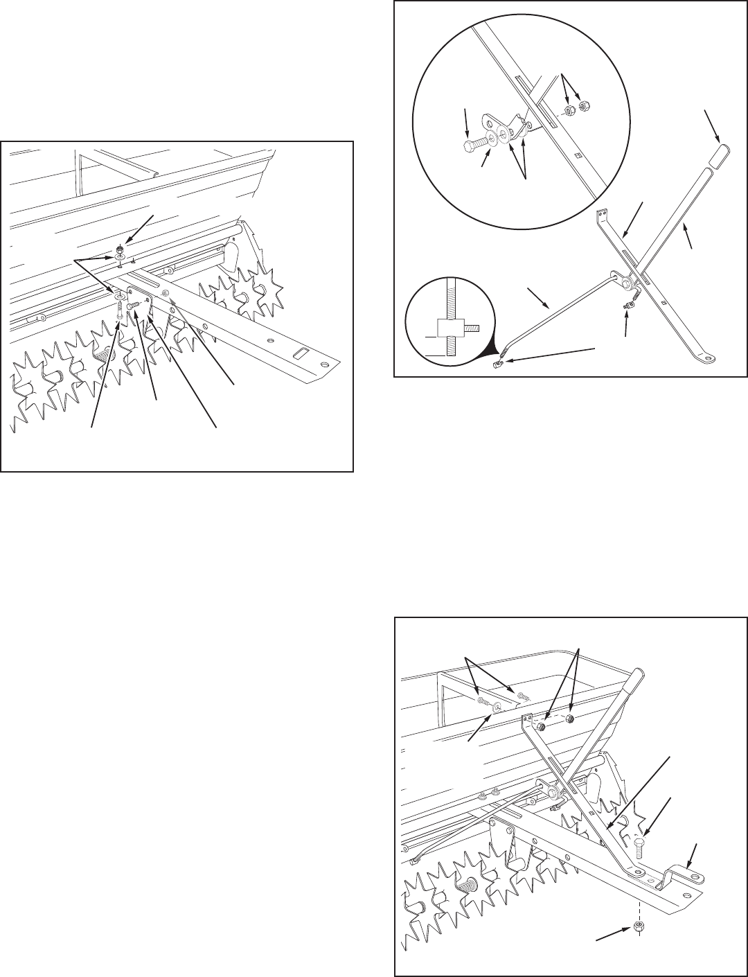
FIGURE 2
1/4" NYLOCK NUT
1/4" NYLOCK NUT
1/4" x 5/8"
HEX BOLT
1/4" FLAT
WASHER
1/4" x 1-3/4"
HEX BOLT
CENTER BRACE
3. Attach the tongueto theframe assembly tube using
two1/4"x1-3/4"hexbolts,four1/4"atwashersand
two1/4"hexnutsasshowningure2.Do not tighten
yet.
4. Attachthetonguetothetwocenterbracesusingfour
1/4"x5/8"hexboltsand1/4"hexnutsasshowningure
2.Do not tighten yet.
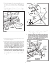
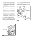
5. Assembletheplasticgripontotheendoftheowcontrol
armasshowningure3.
6. Inserttheowcontrolarmthroughtheslotinthehopper
brace.Placeanylonwasheroneachsideofthearm
andattachittothebrace'sweldedbracketusinga1/4"x
1-1/4"hexbolt,a1/4"atwasherandtwo1/4"hexlock
nutsasshowningure3.Tightenthersthexlocknut
untilthereisnoticeableresistancewhenmovingtheow
controlarm,thentightenthesecondhexlocknut.
7. Placetheowcontrolrodthroughtheholeattheend
oftheowcontrolarm.Assemblethetwoferrulesonto
thethreadedendsoftherodsothatapproximately10
threads(1/2")oftherodextendsthroughtheferrules.
Seegure3.
FIGURE 3
NYLON
WASHER
1/4" NYLOCK
NUTS
1/4" FLAT
WASHER
1/4" x 1-1/4"
HEX BOLT
PLASTIC
GRIP
FERRULE
FLOW
CONTROL
ROD
FLOW
CONTROL
ARM
HOPPER
BRACE
1/2"
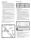
FIGURE 4
3/8" HEX
NYLOCK NUT
1/4" x 5/8"
HEX BOLT
3/8" x 1"
HEX BOLT
1/4" FLAT
WASHER
(ONE ONLY)
1/4" HEX NUT
HOPPER
BRACE
HITCH
BRACKET
8. Attachthehopperbracetothehopperusingtwo1/4"
x5/8"hexbolts,one1/4"atwasherandtwo1/4"hex
nuts.Do not tighten yet.Seegure4.
9 Placetheendofthehitchbracketwithtwoholesdown
throughtheslotinthetongue.Attachthehopperbraceto
thetopofthetongueandthehitchbrackettothebottom
usingone3/8"x1"hexbolt,3/8"lockwasherand3/8"
hexlocknut.Do not tighten yet.Seegure4.


