3
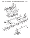
A
B
C D E F
J
K
L
G
H
I
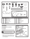
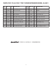
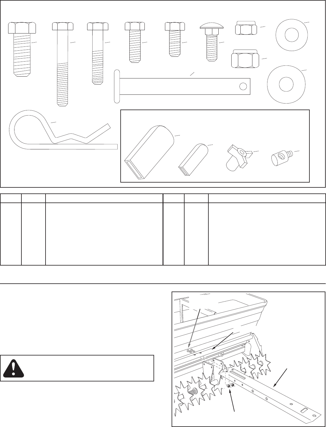
SHOWN FULL SIZE
NOT SHOWN FULL SIZE
O
P
M
N
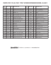
REF. QTY. DESCRIPTION
A 1 HexBolt,3/8"x1"
B 2 HexBolt,1/4"x1-3/4"
C 1 HexBolt,1/4"x1-1/4"
D 2 HexBolt,1/4"x3/4"
E 16 HexBolt,1/4"x5/8"
F 1 CarriageBolt,1/4"x3/4"
G 24 NylockNut,1/4"
H 1 NylockNut,3/8"
REF. QTY. DESCRIPTION
I 10 FlatWasher,1/4"
J 3 NylonWasher
K 1 HitchPin
L 1 HairCotterPin,1/8"
M 1 TransportHandleGrip
N 1 ControlArmGrip
O 1 PlasticKnob
P 2 Ferrule
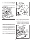
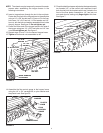
FIGURE 1
1/4" NYLOCK NUT
1/4" x 5/8"
HEX BOLT
TONGUE
FRAME ASSEMBLY TUBE
TOOLS REQUIRED FOR ASSEMBLY
(2)7/16"Wrenches
(2)1/2"Wrenches
(2)9/16"Wrenches
(2)3/4"orAdjustableWrenches(foroptionalwheelremoval
ingure5)
ASSEMBLY
1. Removethehardwarepackandallindividualpartsfrom
thecartonandlayoutasshownonpages2and3.
2. Assembletheendofthetonguetothehopperasshown
ingure1usingtwo1/4"x5/8"hexboltsand1/4"hex
nuts.Theholesarelocatedjustbelowtheframeassembly
tube.Do not tighten yet.
Spikepointsaresharp.Exercisecautionwhen
workingwithhandsnearspikedisks.


