5
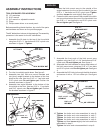
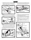
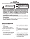
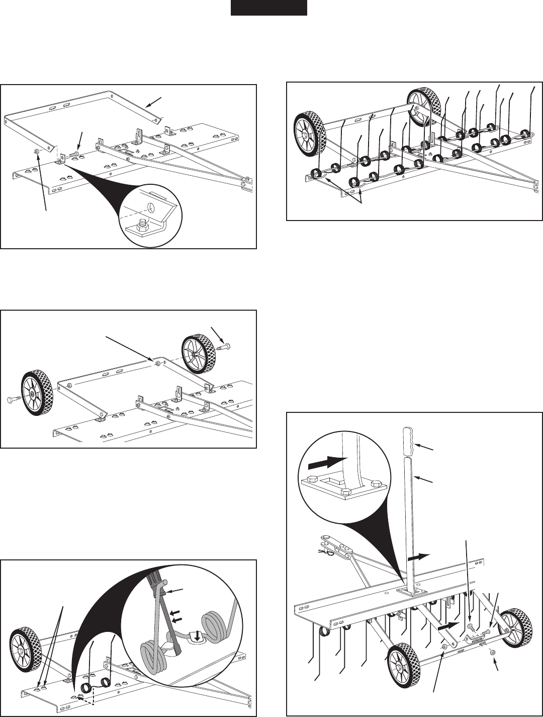
11.Assembletheaxlebracketontheoutsideoftheangle
brackets using two 5/16" x 1" hex bolts and 5/16"
nylocknuts.Theendsoftheaxlebracketmustpoint
asshowningure5.Tightenandthenloosenthe
boltsandnutsslightly.
FIGURE 5
FIGURE 7
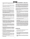
13. Startingwiththefrontrowoftabs,slideaspringtine
undera setoftabs.Insertascrew driver orpunch
downintothetrayandbendeachtabuntiltheend
ofthetabisbentdownevenwiththesurfaceofthe
tray.Repeattoattachallspringtines.Seegure7.
NOTE:Slightloosenessofthespringtinesunderthebent
tabsisnormal.
FIGURE 6
12.Assemblethewheelstotheaxlebracketusingtwo
shoulderboltsandtwo3/8"nylocknuts.Tighten. See
gure6.
14.Assemblethespringalignwiresthroughthefrontand
rearrowsofspringtines,passingthewiresinbetween
thehitchmountarmsandthetineshield.Bendthe
endsofthewirestosecurethem.Seegure8.
FIGURE 9
15. Assembleahitcharmmountbrackettotheaxlebracket
usingtwo5/16"x1"carriagebolts,and5/16"nylock
nuts. Do not tighten yet.Seegure9.
16. Insertthelifthandledownthroughthetineshield.Attach
ittothejustassembledhitcharmmountbracketusing
a5/16"x1"hexboltanda5/16"nylocknut.Tighten.
Seegure9.
17. Positionthehitcharmmountbracketsothatthereis
sidetensiononthelifthandlewhenitislockedinthe
up position. Tightenthenuts.Seegure9.
18. Assemblethegripontotheendofthelifthandle.See
gure9.
FIGURE 8
5/16" NYLOCK NUT
5/16" x 1"
HEX BOLT
AXLE BRACKET
3/8" NYLOCK NUT
SHOULDER BOLT
SPRING ALIGN WIRE
LIFT HANDLE
GRIP
5/16" NYLOCK NUT
5/16" x 1"
HEX BOLT
5/16"
NYLOCK
NUT
5/16" x 1"
CARRIAGE BOLT
ENGLISH
TABS
SCREW
DRIVER


