7
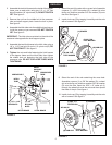
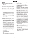
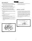
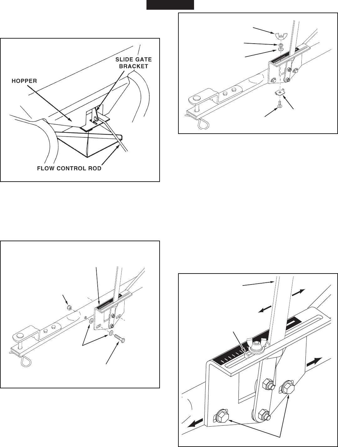
18.Hookthefreeendoftheowcontrolrodthroughthe
holeintheslidegatebracketlocatednearthebottom
ofthehopper.Seegure9.
FIGURE 9
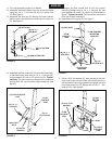
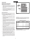
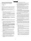
19.Assembletheowcontrolmountingbrackettothehitch
tubeusingtwo1/4"x1-1/2"hexbolts(A),four
5/16"atwashers(F)andtwo1/4"nylocknuts(D)as
showningure10. Do not tighten at this time.
FIGURE 10
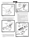
20.Placetheadjustablestop(N)intothe"ON"endoftheslot
inthetopoftheowcontrolmountingbracket.Secure
withthe1/4"x3/4"carriagebolt(C),anylonwasher
(E),a5/16"atwasher(F)andthenylonwingnut(M).
Seegure11.
FIGURE 11
(F) 5/16" FLAT
WASHER
OFF
ON
1
2
3
4
6
7
8
9
10
5
(E) NYLON
WASHER
(C) 1/4" x 3/4"
CARRIAGE BOLT
(M) NYLON
WING NUT
(N) ADJUSTABLE
STOP
ENGLISH
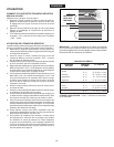
21.Positiontheowcontrolmountingbracket(gure12).
a. Pushonowcontrolarmuntilitlocksin"OFF"
position.
b. Slideowcontrolmountingbracketalongtubeuntil
closureplateinbottomofhopperjustcloses.
c. Snugthemountingboltsjustenoughtoholdow
controlmountingbracketinplace.
d. Setadjustablestopat"5".Pullowcontrolarm
againststop.Verifythatclosureplatehasopened
abouthalfway.
e. Ifclosureplatedoesnotopenhalfway,itmaybe
closedtoofarat"OFF".Adjustpositionofowcontrol
mountingbracketuntilclosureplatewillopenabout
halfwayat"5"andstillclosewhenarmislocked
in"OFF".Tightenmountingbolts.
FIGURE 12
FLOW CONTROL
MOUNTING BRACKET
(A) 1/4" x 1-1/2"
HEX BOLT
(D) 1/4" NYLOCK
NUT
OFF
ON
1
2
3
4
6
7
8
9
10
5
(F) 5/16" FLAT
WASHER
OFF
ON
1
2
3
4
6
7
8
9
10
5
FLOW
CONTROL
ARM
ON
OFF
AJDUSTABLE
STOP
SETTING "5"
MOUNTING BOLTS


