


6
FIGURE 8
FIGURE 9
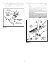
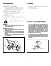
19. Hook the free end of the flow control rod through the
hole in the slide gate bracket located near the
bottom of the hopper. See figure 10.
FIGURE 10
FIGURE 11
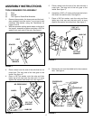
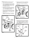
16. Assemble the flow control arm to the flow control
mounting bracket using a 1/4" x 1" hex bolt, two
nylon washers and a 1/4" nylock nut as shown in
figure 8. Tighten carefully. The flow control arm
should be snug, but should pivot with no more than
a slight resistance.
17. Assemble the vinyl grip. See figure 8.
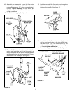
18. Place a 5/16" flat washer onto the end of the flow
control rod. Insert the end of the flow control rod
through the slot in the flow control mounting bracket
and through the hole in the flow control link. Secure
with a 3/32" x 3/4" cotter pin. See figure 9.
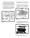
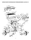
20. Assemble both the flow control mounting bracket
and the short handle tube to the long handle tube.
Use two 1/4" x 1-3/4" hex bolts, four 5/16" flat
washers and two 1/4" nylock nuts as shown in figure
11. Do not tighten at this time.
21. Place a handle grip on each handle. See figure 11.
1/4" x 1-3/4"
HEX BOLT
1/4"
NYLOCK
NUT
HANDLE
TUBE
(SHORT)
HANDLE
TUBE
(LONG)
HANDLE GRIP
FLOW CONTROL
MOUNTING BRACKET
5/16"
FLAT
WASHERS
HOPPER
SLIDE
GATE
BRACKET
FLOW
CONTROL
ROD
FLOW
CONTROL
ROD
FLOW
CONTROL
LINK
3/32"
COTTER
PIN
5/16" FLAT
WASHER
SLOT
1/4" x 1"
HEX BOLT
1/4"
NYLOCK
NUT
FLOW CONTROL
MOUNTING
BRACKET
FLOW
CONTROL
ARM
(2) NYLON
WASHERS
VINYL GRIP