


5
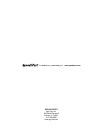
FIGURE 7
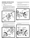
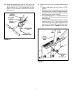
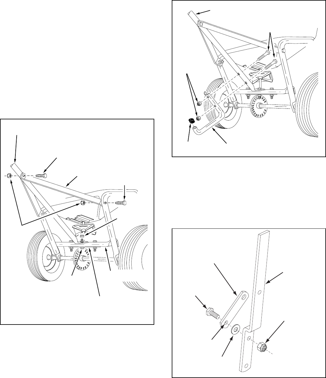
13. Assemble the leg stand tube to the handle tube
(long) using two 1/4" x 1-1/2" hex bolts. Secure
tightly with two 1/4" nylock nuts. See figure 6.
14. Place a vinyl cap over the end of the leg stand tube.
See figure 6.
FIGURE 5
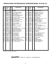
FIGURE 6
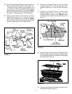
15. Assemble the flow control link (end with small hole)
to the flow control arm using a 1/4" x 1" hex bolt, a
nylon washer and a 1/4" nylock nut as shown in
figure 7. Tighten carefully. The flow control link
should not be loose but should pivot with no more
than slight resistance.
HANDLE TUBE (LONG)
1/4" x 1-1/2"
HEX BOLTS
1/4"
NYLOCK
NUTS
VINYL CAP
LEG STAND TUBE
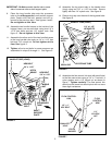
IMPORTANT: Do Not assemble handle tube to same
side of crossover tube as shaft support plate.
9. Place the long handle tube onto the crossover
tube on the side opposite from the shaft support
plate. Fasten with the bolt, washer and nut re-
moved in the previous step. See figures 4 and 5.
Do not tighten at this time.
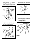
10. Assemble two handle braces to the inside of the
hopper frame, one on each side, using two 1/4" x
1-1/2" hex bolts and two 1/4" nylock nuts. See
figure 5. Do not tighten at this time.
11. Assemble the other end of the two handle braces
to the long handle tube using a 1/4" x 1-1/2" hex
bolt and 1/4" nylock nut. Do not tighten at this
time. See figure 5.
12. Tighten all nuts and bolts in same sequence as
assembled in steps 9 through 11. See figure 5.
MIDDLE
BOLT
MIDDLE
NUT
HANDLE TUBE (LONG)
HEX BOLT
1/4" x 1-1/2"
HEX BOLT
1/4" x 1-1/2"
HITCH
BRACE
1/4"
NYLOCK
NUT
CROSSOVER
TUBE
SHAFT
SUPPORT
PLATE
FLOW CONTROL
LINK
FLOW
CONTROL
ARM
1/4"
NYLOCK
NUT
1/4" x 1"
HEX BOLT
SMALLEST
HOLE
NYLON
WASHER