


How the Frame Generator Works CMI Coding
20 Agilent 81250 ParBERT SONET/SDH Frame Generator, November 2002
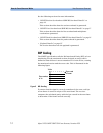
CMI Coding
CMI coding is a method of converting binary data into an electrical
signal. Bits with the value
1
are given bipolar levels (alternating
positive/negative voltages). Bits with the value
0
are represented by
two voltage levels, a negative then positive level, within the same time
span normally used for one digit. This type of code maintains the
signal at the digital clock rate, improving signal synchronization.
For example: Binary
01101011
is converted to:
01 11 00 01 11 01 00 11
NOTE When CMI coding is used, the frequency of the ParBERT has to be
doubled.
NOTE There are a few combinations of settings where the generated
synchronizing pattern is not unique (for example, segment width 8,
STS 48 and STS 192). This can be a problem with very regular CMI
pattern but should not appear with other widths.
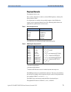
Synchronizing Pattern
ParBERT needs a synchronizing pattern of 48 bits per channel (where
segment width = 1). This pattern is inserted in the D1, D2 and D3 bytes
of the section overhead as long as needed.
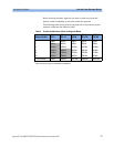
Lower rates are restricted to lower segment widths (see table below).
The following patterns are used:
• For scrambled and non-scrambled frames:
Five fixed bytes:
0xff 0x55 0xaa 0xaa 0x55
Followed by one counter byte:
0xf0
,
0xe1
, ...
0x0f
The complete pattern would be, for example:
0xff 0x55 0xaa 0xaa 0x55 0xf0
• For CMI-coded frames (doubled frequency):
0xf5 0xaa 0x5f