1-15
General Information
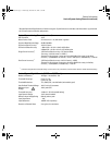
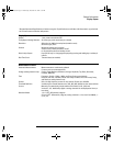
Display System
Display System
Display 7-inch raster monochrome CRT
Throughput of Analog Channels 25 million gray scale vectors/sec per channel
Resolution 255 vertical by 1000 horizontal points (waveform area)
32 levels of gray scale
Controls Waveform intensity on front panel
Vectors on/off; infinite persistence on/off
8 x 10 grid with continuous intensity control
Built-in Help System Key-specific help in 11 languages displayed by pressing and holding key or softkey of
interest
Real Time Clock Time and date (user setable)
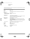
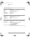
Measurement Features
Automatic Measurements Measurements are continuously updated
Cursors track current measurement
Voltage (analog channels only) Peak-to-Peak, Maximum, Minimum, Average, Amplitude, Top, Base, Overshoot,
Preshoot, RMS (DC)
Time Frequency, Period, + Width, - Width, and Duty Cycle on any channels.
Rise time, Fall time, X at Max (Time at max volts), X at Min (Time at min volts), Delay,
and Phase on analog channels only.
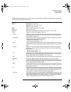
Counter Built-in 5-digit frequency counter on any channel. Counts up to 125 MHz
Threshold Definition Variable by percent and absolute value; 10%, 50%, 90% default for time measurements
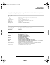
Cursors Manually or automatically placed readout of Horizontal (X,
∆X, 1/∆X) and
Vertical (Y,
∆Y). Additionally digital or analog channels can be displayed as binary or
hex values
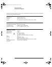
Waveform Math 1-2, 1*2, FFT, differentiate, integrate.
Source of FFT: differentiate, integrate, analog channels 1 or 2 (or 3 or 4 for 54624A), 1-
2, 1+2, 1*2
* Denotes Warranted Specifications, all others are typical. Specifications are valid after a 30-minute warm-up period and
±10 °C from firmware calibration temperature.
service.book Page 15 Wednesday, December 18, 2002 8:35 AM


