6–2
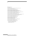
Replacing Assemblies
Use the procedures in this chapter when removing and replacing assemblies and parts
in the Agilent Technologies 54835A/45A oscilloscope.
In general, the procedures that follow are placed in the order to be used to remove a
particular assembly. The procedures listed first are for assemblies that must be removed
first.
ESD Precautions
When using any of the procedures in this chapter you must use proper ESD precautions.
As a minimum you must place the instrument on a properly grounded ESD mat and wear
a properly grounded ESD wrist strap.
CAUTION AVOID DAMAGE TO THE INSTRUMENT!
Failure to implement proper antistatic measures may result in damage to the instrument.
Tools Required
The following tools are required for these procedures.
• Torx drivers: T8, T10, T15
• Socket wrench: 5/8 inch
• Medium size (3/16-in) flat-blade screwdriver
• Nut Drivers: 3/16-in, 9/32-in, 5/16-in, 5/8-in
• Torque driver, 0.34 Nm (3 in-lbs), 5 mm or 3/16-in hex drive
• Torque driver, 0.34 Nm (3 in-lbs), Torx T6 drive
CAUTION REMOVE POWER BEFORE REMOVING OR REPLACING ASSEMBLIES!
Do not remove or replace any circuit board assemblies in this instrument while power is applied.
The assemblies contain components which may be damaged if the assembly is removed or
replaced while power is connected to the instrument.
WARNING SHOCK HAZARD!
To avoid electrical shock, adhere closely to the following procedures. Also, after disconnecting
the power cable, wait at least three minutes for the capacitors on the power supply and sweep
boards to discharge before servicing this instrument. Hazardous voltages exist on the inverter
for the display monitor.


